8
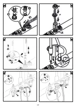
Use of the shower head
(
18
)
To remove the shower head from its support, press
the ring nut down
(1)
and turn it about 45°
(2)
, in order to re-
lease the hose.
After use, put the shower head back in place, press the ring nut
and turn it about 45°.
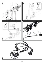
(
19
)
Press the water supply outlet into place as shown,
and fasten it from behind with the headless screw that was pre-
viously removed.
(
4
,
detail 1
).
(
20
)
(1) After inserting the gasket, screw the flexible
hose1/2” F-F (included) into the indicated tap (2).
(3) Then screw the other end of the flexible hose into the cross
cylinder, as shown.
(
21
)
Follow the same procedure to install the other flex-
ible hose.
(
22
)
Then permanently attach, from under the tub edge,
the shower head support and the ring nuts with the screws (
*
).
(
2
3
)
(1)Install the two pins on the shafts of the taps; (2)
turn them until the taps are in the “
closed
” position and fasten
them with hex screws (3).
(
24
)
(1) Install the knobs on the pins and fasten them as
indicated (2). Finally, screw in the chromed pin (3)
.
(
25
)
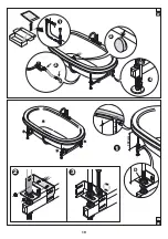
Make the equipotential connection, connecting the
yellow-green cable provided to the faston indicated and attaching
the other end to the terminal on the frame, under the tub
.
Plumbing connections/checks
(
26, detail 1
) Connect the two supply hoses (included) to
the tap fixture.
Put the tub back in its place of installation and connect the
hoses to the floor outlets provided (
detail
3
).
(
27
) Install the drain column, following the instructions in its box.
Note:
if you are going to use a metallic drain column (differ-
ent from the one provided) you must connect it to the e-
quipotential terminal (see
25
).
(
detail 2
) Once the column is assembled, use the shaft to close
the pipe and then install the column control, positioning it as shown
(i.e. with apex facing up).
(
detail
3
) After installing the siphon on the drain pipe, connect
the drain to the floor using a hose.
Before attaching the tub to the floor, check that none of the
connections leak.
Permanently attach the feet to the floor (
27, detail 4
).
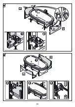
Installation of panels
(where included)
(
28, detail 1
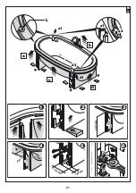
) For each leg, adjust the position of the upper
nut D so that the distance between the bracket and the wood skirt
is as indicated.
Note:
measure from the bottom of the groove (on the lower
part of the wood skirt) to the upper part of the bracket.
The nuts thus positioned provide a reference position for
the subsequent installation of the panels.
(
detail 2-
3
) Install the 4 brackets with pins, as shown, and fas-
ten them so that the pins are located at about the halfway point of
the slots on the brackets of the legs.
Side panels
(
29
) Unscrew the lower nut so as to lower the previously
installed brackets. Then set the side panel
a
near the tub and
check that:
- the peg on the wood skirt (a2) fits into the grooved part (a1)
of the panel.
- the pins on the panel fit into the side slots of the previously
installed brackets
(
detail 1
)
.
Then attach the panel to the two brackets using the nuts provided.
Do the same for panel
d
.
Front panels
(
3
0, detail 1
) Remove the shower head from its support,
extracting its hose all the way out.
(
detail 2
) Set the front panel
b
on the tub and insert the pins in
the side slots of the brackets.
(
detail
3
) Check that the shower head hose moves freely, then
place the shower head back in its support.
Then attach the panel to the two brackets using the nuts provided.
Do the same for panel
c
.
Adjustment and fastening of panels
(
3
1, detail 1-2
) Raise the side panel
a
until its upper edge
enters about 5 mm into the groove of the wood skirt;
check that
the peg on the wood skirt (a2) fits into the grooved part (a1)
of the panel.
Then horizontally move the panel so that the upper edge con-
tacts the two stops “L” (one per side).
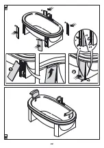
(
detail 2-
3
) Using suitable spacers, lift the panel so that the dis-
tance between wood skirt and the lower side of the panel is as
indicated.
Summary of Contents for AnimaDesign
Page 2: ......
Page 3: ...Italiano 4 English 7 Fran ais 10 Deutsch 23 Espa ol 26 29 AnimaDesign Index...
Page 13: ...13 189 190 99 100 60 1 99 189 60 1a...
Page 14: ...14 50 cm G G 2 60 cm G G 2a 2 1 4 5 3 3...
Page 15: ...15 7 8 1 2 3 9 1 2 6 1 3 2 A B C 4 5...
Page 16: ...16 1 2 10 2 1 3 4 H I F G E J K L M 11 12 L M 2 1 13 14 1 J J 2 15...
Page 17: ...17 1 2 3 1 2 3 20 21 1 M5x5 mm 2 19 45 1 3 2 18 H H I K J H I 2 2 1 16 G H F E 17...
Page 18: ...18 1 2 3 22 23 1 2 3 24 25 3 2 1 26...
Page 19: ...19 333 mm D 1 2 3 28 2 3 4 1 27...
Page 20: ...20 a a1 d1 a2 d 1 2 d2 a1 a2 29 3 b c 2 1 4 30...
Page 21: ...21 150 mm 48 mm 90 c b a d a1 a2 d2 d1 493 mm 1 2 4 5 6 3 a1 a2 90 90 L 31...
Page 22: ...22 1 2 r s s1 r1 32 33...
Page 31: ...31 1 d 30 1 2 b 3 31 1 2 5 a2 a1 L 2 3 b c 4 5 6 d 32 1 2 r1 r 2 s s1 33...


