REL 1.0
Page 1 of 89
RZ/G1M/G1N Qseven Development Platform Hardware User Guide
iWave Systems Technologies Pvt. Ltd.
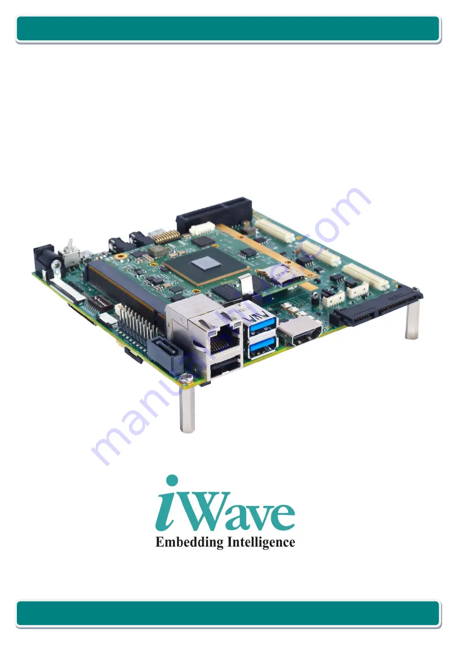
iW-RainboW-G20D
RZ/G1M/G1N Qseven Development Platform
Hardware User Guide
Page 1: ...REL 1 0 Page 1 of 89 RZ G1M G1N Qseven Development Platform Hardware User Guide iWave Systems Technologies Pvt Ltd iW RainboW G20D RZ G1M G1N Qseven Development Platform Hardware User Guide...
Page 2: ...TICE This document contains proprietary material for the sole use of the intended recipient s Do not read this document if you are not the intended recipient Any review use distribution or disclosure...
Page 3: ...silicon errata and associated issues Trademarks All registered trademarks product names mentioned in this publication are the property of their respective owners and used for identification purposes...
Page 4: ...ebug UART Port 34 2 5 2 Data UART Header 35 2 6 High Speed Interface Features 36 2 6 1 USB3 0 Port0 Host 36 2 6 2 PCIe Channel0 Port 37 2 6 3 SATA Channel0 Port Optional 42 2 7 Communication Interface...
Page 5: ...ader 77 4 TECHNICAL SPECIFICATION 78 4 1 Electrical Characteristics 78 4 1 1 Power Input Requirement 78 4 1 2 Power Output Specification 79 4 2 Environmental Characteristics 80 4 2 1 Environmental Spe...
Page 6: ...ure 22 SOM Expansion Connectors 61 Figure 23 Carrier Board Expansion Connectors 62 Figure 24 RZ G1M G1N Camera Add On Module Block Diagram 68 Figure 25 Camera Add On Module Expansion Connectors 69 Fig...
Page 7: ...le 13 SD MMC Connector Pin Out 50 Table 14 CAN Header Pin Out 51 Table 15 Audio OUT Jack Pin Out 53 Table 16 Audio IN Jack Pin Out 53 Table 17 7 RGB LCD Connector Pin Out 55 Table 18 Capacitive Touch...
Page 8: ...r and the Qseven carrier board with 7 Capacitive Touch LCD The development board can be used for quick prototyping of various applications targeted by the RZ G1M G1N processor With the 120mmx120mm Nan...
Page 9: ...Board PCIe Peripheral Component Interconnect Express PTH Plated Through hole PWM Pulse Width Modulation RTC Real Time Clock SATA Serial AT Attachment SCIF Serial Communication Interface with FIFO SDIO...
Page 10: ...ide Semiconductor Signal DIFF Differential Signal TMDS Transition Minimized Differential Signalling OD Open Drain Signal OC Open Collector Signal Analog Analog Signal Power Power Pin PU Pull Up PD Pul...
Page 11: ...0 SDHI2 USB1_HUB_2 SCIF0 JTAG SCIFB1 CAN1 3V 7 RGB Capacitive LCD Conn LVDS0 LVDS Receiver RGB 24bit LVDS DU0 PCIe EtherAVB USB1_HUB_1 SATA0 SATA1 Control Signals SMBUS GP1_I2C Port2 Top Ethernet Top...
Page 12: ...terface Features USB 3 0 USB 2 0 Host x 1 Port through USB 3 0 Type A Connector PCIe x 1 Port through x4 connector or Mini PCIe connector1 SATA x 1 Port through 22pin Serial ATA Connector Optional 2 C...
Page 13: ...SATA connector is supported always in Qseven carrier board hardware If Qseven SOM supports SATA interface on Qseven Edge connector then SATA can be tested in Qseven carrier board In RZ G1M G1N CPU ba...
Page 14: ...er board supports 230Pin Qseven MXM Edge mating connector for Qseven SOM attachment This standard 230 pin robust connector is capable of handling high speed serialized signals and can be used for size...
Page 15: ...link status LED This pin is connected to D15 Green LED 8 GBE_LINK1000 GPHY_LINK_LED2 Gigabit Ethernet link status LED This pin is connected to D16 Green LED 9 GBE_MDI1 GPHY_BTXRXM IO DIFF Gigabit Ethe...
Page 16: ...nected to Expansion Connector3 J14 10th Pin 20 PWRBTN PWRBTN Power Button output This pin is connected from Push button SW3 for SOM On Off control 21 SLP_BTN NA NC in RZ G1M G1N Qseven SOM This pin is...
Page 17: ...Qseven SOM This pin connected to 22pin SATA Connector J25 for SATA Channel0 Receive differential pair positive 36 SATA1_RX NA NC in RZ G1M G1N Qseven SOM This pin connected to 7pin SATA Connector J21...
Page 18: ...to SD MMC connector J30 51 SDIO_DAT2 SD2_DAT2 GP6_12 IO 3 3V CMOS SD2 Data2 This pin is connected to SD MMC connector J30 52 SDIO_DAT5 NA NC in RZ G1M G1N Qseven SOM This pin is connected to SD MMC c...
Page 19: ...Data This pin is connected to I2S audio codec 66 GP0_I2C_CLK I2C2_SCL GP2_6 I 3 3V OD I2C2 clock This pin is connected to I2S Audio Codec Capacitive touch connector Resistive touch connector and Expa...
Page 20: ...Host Port0 Receive Differential pair positive This pin is connected to Dual stack USB3 0 TypeA connector J23 bottom port 79 USB_6_7_OC NA Over current sense signal for USB3 0 Host Port0 This pin is co...
Page 21: ...0 TypeA connector J23 bottom port 89 USB_P3 NA NC in RZ G1M G1N Qseven SOM This pin is connected to Dual stack USB3 0 TypeA connector J23 top port in carrier board 90 USB_P2 USB_P2 IO DIFF USB 2 0 Ho...
Page 22: ..._TX1 LVDS_B1 NA NC in RZ G1M G1N Qseven SOM This pin is connected to secondary LVDS connector J27 in carrier board 105 eDP0_TX1 LVDS_A1 DU0_LVDS_CH1_N IO DIFF LVDS primary channel differential pair1 n...
Page 23: ...e This pin is connected to LVDS Receiver 120 eDP1_AUX LVDS_B_CLK NA NC in RZ G1M G1N Qseven SOM This pin is connected to secondary LVDS connector in carrier board 121 eDP0_AUX LVDS_A_CLK DU0_LVDS_CLK_...
Page 24: ...his pin is directly connected to Expansion Connector3 J14 23rd Pin in carrier board 133 DP_LANE3 TMDS_CLK NA NC in RZ G1M G1N Qseven SOM This pin is connected to HDMI connector J24 in carrier board 13...
Page 25: ...onnected to HDMI connector J24 in carrier board 150 HDMI_CTRL_DAT NA NC in RZ G1M G1N Qseven SOM This pin is connected to HDMI connector J24 in carrier board 151 DP_LANE0 TMDS_LANE2 NA NC in RZ G1M G1...
Page 26: ...even SOM This pin is connected to PCIex4 connector J4 in carrier board 165 GND GND Power Ground 166 GND GND Power Ground 167 PCIE2_TX NA NC in RZ G1M G1N Qseven SOM This pin is connected to PCIex4 con...
Page 27: ...connected from Data UART Header J1 02nd Pin 179 PCIE0_TX PCIe1_TXP I DIFF PCIe Channel0 Transmit data output positive This pin is connected to PCIe x 4 connector J4 or Mini PCIe connector J26 through...
Page 28: ...t populated 189 LPC_CLK GPIO4 Q7_GPIO4_ GP2_3 IO 3 3V CMOS General purpose Input Output4 This GPIO is used for CAN0 Transceiver Power down control and connected to CAN transceiver Note This pin is als...
Page 29: ...to Expansion connector3 J14 46th Pin 202 SPI_CS1 MSIOF2_SS1 GP2_17 I 3 3V CMOS SPI Chip Select2 This pin is also connected to Expansion connector3 J14 49th Pin 203 SPI_SCK MSIOF2_SCK GP1_13 I 3 3V CMO...
Page 30: ...12 VCC VCC_5V O 5V Power Supply Voltage 213 VCC VCC_5V O 5V Power Supply Voltage 214 VCC VCC_5V O 5V Power Supply Voltage 215 VCC VCC_5V O 5V Power Supply Voltage 216 VCC VCC_5V O 5V Power Supply Volt...
Page 31: ...hnologies Pvt Ltd 2 4 On Board Switches 2 4 1 Power ON OFF Switch The RZ G1M G1N Qseven carrier board has power ON OFF switch SW1 to control the Main power Input On Off functionality This power ON OFF...
Page 32: ...h bit of this switch is used to select the different features or modes This Board configuration switch is physically located at the top of the board as shown below Figure 4 Board Configuration Switch...
Page 33: ...is connected to PCIex4 Slot 7 DEBUG_SELECT Debug Port is selected as UART 8 USB_ID USB0 acts as Host mode or Device mode based on the connected cable in USB MicroAB connector J2 USB0 is forced to Host...
Page 34: ...ro AB Connector can be used for Debug purpose which is physically located at the top of the board as shown below Figure 6 Debug UART As per Qseven specification version 2 0 Debug UART interface and JT...
Page 35: ...rd as shown below Number of Pins 6 Connector Part number 5 146280 6 from TE Connectivity Mating Connector 534237 4 from TE Connectivity Figure 7 Data UART Header Table 5 Data UART Header Pin Out Pin N...
Page 36: ...ce takes more than 900mA current this power switch limits the current to constant mode and sends the over current indication signal to the over current indicator pin of Qseven MXM connector USB port 6...
Page 37: ...PCIe channel0 signals of Qseven MXM connector is connected to 1 2 Multiplexer Demultiplexer switch and then one output of this Multiplexer Demultiplexer switch is connected to PCIex4 connector and ot...
Page 38: ...oltage A9 3 3V VPCIe_3V3 O 3 3V Power 3 3V Supply Voltage B9 TRST NC NC A10 3 3V VPCIe_3V3 O 3 3V Power 3 3V Supply Voltage B10 3V3AUX VAUX_3V3 O 3 3V Power 3 3V Supply Voltage A11 PERST GPIO_PCIe_RST...
Page 39: ...Transmit pair positive A24 GND GND Power Ground B24 PCIE2_TX NC NC PCIe Port 2 Transmit pair negative A25 PCIE2_RX NC NC PCIe Port 2 Receive pair positive B25 GND GND Power Ground A26 PCIE2_RX NC NC...
Page 40: ...d as shown below Figure 10 Mini PCIe Connector Table 8 Mini PCIe Connector Pin Out Pin No Pin Name Signal Name Signal Type Termination Description 1 PCIe_WAKE GPIO_PCIe_WAKE GP5_11 O 3 3V CMOS PCIe WA...
Page 41: ...1 5V VCC_1V5 O 1 5V Power 1 5V Supply Voltage 29 GND GND Power Ground 30 SMB_CLK I2C5_SCL O 3 3V CMOS SMB Clock 31 PCIE0_TX PCIE0_TX O DIFF PCIe Channel0 Transmit pair negative 32 SMB_DATA I2C5_SDA I...
Page 42: ...face If Qseven SOM supports SATA channel0 then it can be tested through this 22pin SATA connector J25 The RZ G1M G1N Qseven SOM doesn t support SATA channel0 interface by default and it is only the op...
Page 43: ...Differential pair negative S6 SATA1_RXP SATA1_RXP I DIFF SATA Receive Differential pair positive S7 GND GND Power Ground P1 V33 VCC_3V3 O 3 3V Power 3 3V Supply Voltage P2 V33 VCC_3V3 O 3 3V Power 3...
Page 44: ...gh RZ G1M G1N CPU s EtherAVB interface which supports 100 1000Mbps Ethernet The Ethernet PHY output signals from Qseven MXM connector is directly connected to RJ45 Magjack J22 Also it supports Speed Y...
Page 45: ...ormer Centre Tap 2 7 CT4 TRCT4 Transformer Centre Tap 4 8 TRX3 GPHY_DTXRXP IO DIFF Gigabit Ethernet MDI differential pair 3 positive 9 TRX3 GPHY_DTXRXM IO DIFF Gigabit Ethernet MDI differential pair 3...
Page 46: ...h limits the current above 500mA If connected USB2 0 device takes more than 500mA current this power switch limits the current to constant mode and sends the over current indication signal to the over...
Page 47: ...2 0 connector is connected through current limit power switch which can be used to switch On Off the power based on the device or Host and also limits the current above 500mA in host mode The connecte...
Page 48: ...t1 OTG Table 12 USB2 0 Port1 OTG Connector Pin Out Pin No Pin Name Signal Name Signal Type Termination Description 1 VCC_5V V_OTG I 5V Power 5V Supply Voltage 2 USB_DM USB_OTG IO DIFF USB OTG Data neg...
Page 49: ...rt Standard SD interface This connector supports up to 4 bit data transfer with card detect and write protect Also it supports SDIO activity Green LED D8 on board for SDIO bus transfer indication The...
Page 50: ...s pin is connected from Qseven MXM connector 54th pin 6 GND GND Power Ground 7 SD_DATA6 NC NC in RZ G1M G1N carrier board Note This pin is connected from Qseven MXM connector 55th pin 8 SD_CLK SD2_CLK...
Page 51: ...189th Pin of the Qseven MXM connector This CAN header is physically located at the top of the board as shown below Number of Pins 6 Connector Part number 53047 0610 from Molex Mating Connector 051021...
Page 52: ...n support I2S format This four wire I2S signals from Qseven MXM connector is connected to I2S Audio Codec SGTL5000 to support Headphone Stereo output and Mono Mic input which is supported through 3 5m...
Page 53: ...2 HP_Left HP_L O Analog Headphone Output Left 3 HP_Right HP_R O Analog Headphone Output Right 4 HP_Detect Q7_GPIO3_ GP2_19 I 3 3V CMOS 10K PU Headphone detect Signal 5 NC NC NC Table 16 Audio IN Jack...
Page 54: ...ch is connected to LVDS0 port of Qseven MXM connector is used for this LCD interface This LVDS0 interface signals are directly connected to LVDS transmitter DS90CF384A in carrier board which converts...
Page 55: ..._B5 O 3 3V CMOS Display Blue Data 5 16 VSS4 GND Power Ground 17 B2 DIS_B4 O 3 3V CMOS Display Blue Data 4 18 B1 DIS_B3 O 3 3V CMOS Display Blue Data 3 19 B0 DIS_B2 O 3 3V CMOS Display Blue Data 2 LSB...
Page 56: ...n Description 1 VSS1 VSS1 Power Ground 2 VDD VDD O 3 3V Power 3 3V Supply voltage 3 I2C_SCL I2C2_SCL GP2_6 O 3 3V OD I2C2 Clock Signal 4 NC NC 5 I2C_SDA I2C2_SDA GP2_7 IO 3 3V OD I2C2 Data Signal 6 NC...
Page 57: ...s SPI interface signals from Qseven MXM connector is connected to SPI Flash SST25VF016B 50 and operating at 3 3V Level 2 9 2 RTC Coin Cell Holder The RZ G1M G1N Qseven carrier board supports Coin Cell...
Page 58: ...M5 interface is used for Fan speed control PWM This Fan Header J19 is physically located at the top of the board as shown below Number of Pins 6 Connector Part number 53047 0610 from Molex Mating Conn...
Page 59: ...ed to JTAG Header J16 through 3 3V level Buffer This JTAG Header J16 is physically located at the top of the board as shown below As per Qseven specification version 2 0 Debug UART interface and JTAG...
Page 60: ...TAG test reset signal 4 GND GND Power Ground 5 JTAG_TDI JTAG_TDI I 3 3V CMOS JTAG test data Input 6 GND GND Power Ground 7 JTAG_TMS JTAG_TMS I 3 3V CMOS 10K PU JTAG test mode select 8 GND GND Power Gr...
Page 61: ...oard has two 80pin Expansion Connectors for mating with RZ G1M G1N Qseven SOM This SOM Expansion connector 1 2 J15 J10 pins are one to one directly connected to Carrier board Expansion connector 1 2 J...
Page 62: ...ven MXM connector is directly connected to Expansion Connector3 J14 Also on board 5V 3 3V 1 5V power is connected to this connector for Add On Module power These Expansion connectors J17 J9 J14 are ph...
Page 63: ...NC in RZ G1M G1N carrier board Note This pin is connected from Qseven MXM connector 19th pin 11 SMB_ALERT NC in RZ G1M G1N carrier board Note This pin is connected to Qseven MXM connector 64th pin 12...
Page 64: ...nnector 134th pin 26 GND Power Ground 27 GND Power Ground 28 LID_BTN NC in RZ G1M G1N carrier board Note This pin is connected to Qseven MXM connector 22nd pin 29 RSVD DP3 NC in RZ G1M G1N carrier boa...
Page 65: ...n is connected to Qseven MXM connector 191st pin through resistor and default populated 41 Q7_GPIO3_ GP2_19 I 3 3V CMOS 10K PU Qseven General purpose Input Output3 This pin is connected from Audio Out...
Page 66: ...connected from Qseven MXM connector 202nd pin 50 GND Power Ground 51 MSIOF2_SCK GP1_13 I 3 3V CMOS SPI Clock This Pin is shared to On Board SPI Flash Note This pin is connected from Qseven MXM connec...
Page 67: ...ower Ground 75 GND Power Ground 76 GND Power Ground 77 I2C5_SCL O 3 3V OD I2C5 clock Note This pin is connected from Qseven MXM Connector 60th pin through resistor and default populated 78 I2C2_SCL GP...
Page 68: ...xpansion Connector 1 Expansion Connector 2 Expansion Connector 3 Video Decoder VIN0 8bit TV IN RCA Jack 8bit CMOS Camera Connector HDMI In Connector Optional VIN2 8bit CAN Transceiver CAN1 Header RS23...
Page 69: ...rt 8bit CMOS Camera 8bit VIN2 x 1 Port HDMI Output through HDMI Transmitter 24bpp DU1 x 1 Port HDMI Input through HDMI Receiver 16bit VIN1 x1 Port Optional 16bit CMOS Camera 16bit VIN1 x 1 Port Option...
Page 70: ...port of RZ G1M G1N CPU through expansion connector1 Also RZ G1M G1N CPU s I2C5 interface is connected to TV In Decoder for control configuration This Analog Video TV IN RCA Jack J6 is physically loca...
Page 71: ...for control configuration External reference clock for camera is provided by using on board 26MHz Oscillator This Camera connector J8 is physically located on top of the board as shown below Compatibl...
Page 72: ...to enable the camera always 9 HSYNC VI2_HSYNC I 2 8V CMOS VIN2 Camera Horizontal Synchronization 10 DVDD DVDD O 1 8V Power Digital Power Supply 11 DOVDD DOVDD O 2 8V Power Camera IO Power Supply 12 DA...
Page 73: ...ection circuitry HDMI Output connector J10 is physically located on top of the board as shown below Figure 28 HDMI Output Table 24 HDMI Output connector Pin Out Pin No Pin Name Signal Name Signal Type...
Page 74: ...The RZ G1M G1N Camera Add On Module optionally supports HDMI input port using ADV7612WBSWZ HDMI receiver This HDMI receiver converts HDMI input into 16bit CMOS camera signals and connected to RZ G1M G...
Page 75: ...in Rs of the CAN Bus transceiver is connected to RZ G1M G1N CPU GPIO GP0_4 from expansion connector2 This CAN header J3 is physically located at the top of the board as shown below Number of Pins 6 Co...
Page 76: ...vel into RS232 level and connected to 6pin header J2 This Data UART header is physically located at the top of the board as shown below Number of Pins 6 Connector Part number 5 146280 6 from TE Connec...
Page 77: ...6pin header J1 This high Speed UART header is physically located at the top of the board as shown below Number of Pins 6 Connector Part number 5 146280 6 Mating Connector 5 534237 4 Figure 31 High Sp...
Page 78: ...o work with a 12V external power and uses on board voltage regulators for internal power management 12V power input from an external power supply is connected to the Qseven Carrier Board through Power...
Page 79: ...only after the RZ G1M G1N CPU is powered ON completely in the RZ G1M G1N Qseven SOM This is to ensure that there is no back voltage leakage from any supply on the board towards the RZ G1M G1N CPU IO...
Page 80: ...ture range 0 C 60 C iWave only guarantees the component selection for the given operating temperature 4 2 2 RoHS Compliance iWave s RZ G1M G1N Qseven Development Platform is designed by using RoHS com...
Page 81: ...0mm Qseven Carrier Board mechanical dimension is shown below Figure 33 RZ G1M G1N Qseven carrier board Mechanical dimension Top View The RZ G1M G1N Qseven carrier board PCB thickness is 1 6mm 0 1mm to...
Page 82: ...ew 4 3 3 Guidelines to insert the Qseven SOM into Carrier Board Make sure that power is not provided to the carrier board Insert the Qseven module in to the MXM connector at an angle of 30 as shown be...
Page 83: ...OM Linux Development Platform with 1GB RAM 4GB eMMC and without 7 Capacitive touch LCD display Commercial RZ G1N CPU based Qseven Development Platform iW G20D Q702 3D001G E004G LCC RZ G1N Qseven SOM L...
Page 84: ...tegration Procedure The RZ G1M G1N Camera Add On Module comes with the following accessories Table 33 Camera Add On Module Accessories SL No Accessory Description Image Quantity 1 Camera Add On Module...
Page 85: ...G1M G1N Camera Add On Module in to RZ G1M G1N Development platform 1 Insert M2 5x15mm pan head screw from RZ G1M G1N Qseven carrier board bottom side as shown below Figure 37 Insert Pan Head Screw 2...
Page 86: ...Z G1M G1N Qseven carrier board through the M2 5mm screw as shown below Press and make sure all three mating connector of Camera Add On Module is inserted properly into the carrier board Expansion conn...
Page 87: ...t Ltd 5 Insert the M2 5mm Split lock washer above the Non metallic flat washer as shown below Figure 41 Insert Split Lock Washer 6 Finally tighten the M2 5mm nut into screw as shown below to finish th...
Page 88: ...re Follow the below procedure to connect the 8bit CMOS camera in to the RZ G1M G1N Camera Add On Module 1 Connect the 8bit CMOS camera in to the camera connector J8 of Camera Add On Module as shown be...
Page 89: ...REL 1 0 Page 89 of 89 RZ G1M G1N Qseven Development Platform Hardware User Guide iWave Systems Technologies Pvt Ltd...