Operation Manual -
PoWerMaster®
2400 – 30 - 90 kVA
Transport and Installation
Document no. 578.650BB
Page 23 of 91
4.8
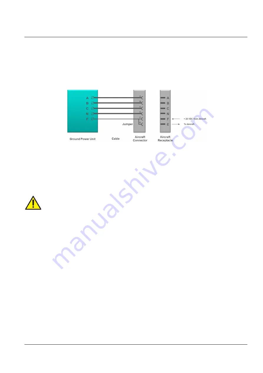
400 Hz Interlock
The interlock safety system ensures that the output contactor stays engaged as long as the aircraft
connector is inserted into the aircraft receptacle. The aircraft provides 28 VDC on the F terminal with
respect to the 400 Hz neutral terminal.
Fig. 4.8.1 Standard wiring diagram for civil aircraft
For service, maintenance and test purposes, the interlock system can be by-passed via the display setup.
To ensure personal health and safety, the ground power unit automatically returns to its initial interlock
mode, once it receives 28 VDC at the F terminal, e.g. when the ground power unit is connected to an
aircraft.
To ensure personal health and safety, the interlock safety system must always be activated
unless the ground power unit is undergoing service, maintenance or test by qualified
personnel.
4.9
Control Interface (Remote I/O Terminals)
Using the Remote I/O terminals, situated behind the front door to the left, it is possible to interface to:
•
External Emergency Stop (EPO).
The external EPO input A2: X14 is a 24 VDC input, either by using the internal 24 VDC supply
or an external 24 VDC voltage. The SW1 “EPO JUMPER” (at the top right corner of the A2
Module) is then removed. Refer to Fig. 4.9.1 for connection.
•
E&F Interlock F Pin.
•
External Start / Stop.
Remote Start must be N.O. The remote Stop may be either N.O. / N.C., this can be
selected/changed using the Set-Up menu.
•
90 % Insertion Switch / Split “F” pin in aircraft connector.
The 90% Insertion switch (N.O. contact set) in the aircraft connector is supplied with +24 VDC
from the Hobart
PoWerMaster®
2400. The voltage is returned to the input once the plug is
inserted at least 90% of the way into the aircraft receptacle.


