OM-2245 / Operation and Maintenance Manual
ITW GSE 4400 / 400 Hz. Generator Set
March 15, 2015
Chapter 1-1
Page 18
11)Active Rectifier Unit (ARU)
The ARU provides a regulated output voltage of 28.5 VDC. Input power is provided to the DC components
from the 115/200 volt, 400 Hz generator set, through an input contactor. The output contactor provides DC
power to the load. Both 400 Hz & 28 VDC outputs can be used simultaneously. The 28 VDC power is
provided by an Active Rectifier Unit which is supplied from the 400 Hz output. The 28 VDC output voltage is
controlled regardless of any variations in the 400 Hz input voltage. The total continuous amount of power from
the unit is calculated as the sum of the 400 Hz and 28 VDC outputs and cannot exceed units 400 Hz power
rating.
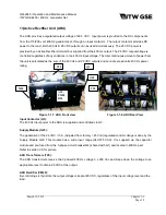
Figure 1-1-7 ARU Front view
Figure 1-1-8 ARU Rear View
Input Contactor (Q3):
The 400 Hz input power to the ARU is supplied and controlled via Q3.
Supply Module (G20):
The generation of the 24 VDC / 10 A (Adjusted from factory = 25 Volt) regulated control voltage is done by the
Supply Module G20. This module has a wide input range (340-575 VAC). It is supplied via the capacitor
module and pre-fused from the 3-phase circuit breaker Q4 (shared with G1) and located in 400 Hz part.
Refer to section 3.0 for picture.
ARU Transformers (T20):
The ARU transformers receive the 3 phased 400 Hz voltage 3 x 200 Vac and steps down the voltage to an
appropriate level to obtain 28 VDC at the output.
ARU Rectifier (PM20):
By controlling six thyristors the output voltage is kept at 28 VDC, regardless of the input voltage level and the
load.
Q3
T20
A20,
PM20
R20
C20
M20
G20

