OM-2245 / Operation and Maintenance Manual
ITW GSE 4400 / 400 Hz. Generator Set
March 15, 2015
Chapter 3-1
Page 5
WARNING
To prevent personal injury, keep fingers and hands clear of generator assembly until
the armature is block into place to prevent rotation.
b
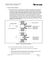
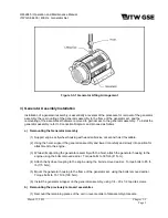
Attempt to loosen exciter armature on shaft by rotating it slightly back and forth. If armature
cannot be loosened by hand, use two M10-1.5 hex-head bolts as shown in Figure 3-1-4 to
force the exciter armature off the shaft. Turn each of the two screws a few turns at a time into
the threaded holes of the diode mounting plate until the exciter armature is sufficiently
loosened from the shaft to be removed from it by hand. Remove it slowly from the shaft and
at the same time observe the following
CAUTION.
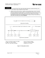
1. Stud, 1/4-28 UNF 2A, Grade 5 or 8 ONLY
2. Adapter, 3/4" Round CR Steel
3. Nut, 1/2-13 Hex, Steel (3 required)
4. Rod, 1/2" Round, CR Steel
5. Hammer, 2" Round, CR Steel
6. Washer, Flat, 1/2" Steel
Figure 3-1-3 Sling Hammer Puller

