background image

OM-2245 / Operation and Maintenance Manual
ITW GSE 4400 / 400 Hz. Generator Set

March 15, 2015

Chapter 1-1

Page 17

10) Cold Weather Starting System (BH1)

The intake air heater, located on the intake manifold, is used for starting the engine at very cold 
temperatures and reduces the white smoke associated with a cold start.  The intake air heater (or grid 
heater) is energized or de-energized from a power relay controlled by the ECM.  The amount of time the 
air intake heaters stay on, in the preheat phase, is a function of the intake manifold temperature at start 
up.  (The pre-heat time increases with colder intake manifold temperatures).  The maximum duration of 
the pre-heat phase is around 30 seconds. 

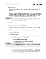
CAUTION

Never use an ether start system in conjunction with the air intake heater.

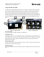
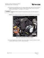
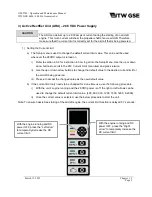
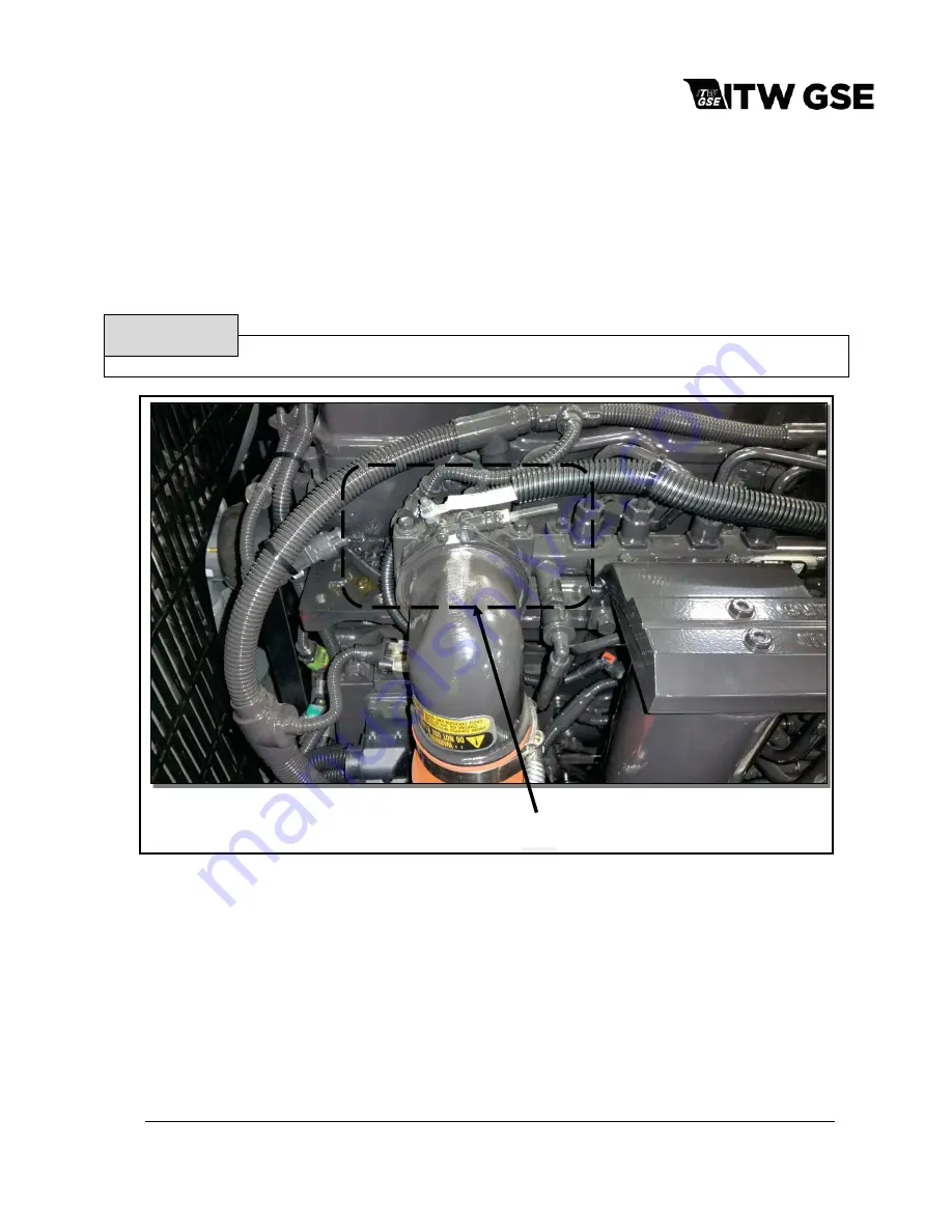
Figure 1-1-6: Air Intake Heater

Air Intake Heater

Summary of Contents for 4400

Page 1: ...ghway 41 North Ɣ Palmetto FL 34221 Ɣ U S A T toll free in US 800 899 1841 Ɣ T International 1 941 721 1000 Ɣ E sales itwgse us Manual ITW GSE 4400 60 90 kVA 3 Phase 115 Volt 400 Hz Generator Set Series no 500100 Type 4400 it s all about connections ...

Page 2: ......

Page 3: ...he manual and to locate information contained in it Its style and arrangement are very similar to commercial aircraft manuals The manual is divided into five chapters plus an appendices Each chapter is divided into as many sections as required Each new section starts with page 1 Each page is identified by chapter section and page number which are located in the lower outside corner When informatio...

Page 4: ...rtment by mail telephone FAX or E Mail Write ITW GSE Service Department 11001 US Highway 41 North Palmetto FL 34221 U S A Call Inside U S A 866 845 0441 Parts 877 874 5322 Service Call From Foreign Countries 941 721 1092 Technical Support 941 721 1000 Spare Parts FAX inside U S A 800 367 4945 FAX From Foreign Countries 941 721 1091 E Mail technicalsupport itwgse us parts itwgse us Web Page www itw...

Page 5: ...ly observe all safety rules and take precautionary actions Safe practices have been developed from past experience in the use of power source equipment While certain practices below apply only to electrically powered equipment other practices apply to engine driven equipment and some practices to both 2 Shock Prevention Bare conductors terminals in the output circuit or ungrounded electrically liv...

Page 6: ...become hot enough to cause fires by self destruction or by causing nearby combustibles to ignite b Batteries Batteries may explode and or give off flammable hydrogen gas Acid and arcing from a ruptured battery can cause fires and additional failures When servicing do not smoke cause sparking or use open flame near the battery c Engine Fuel Use only approved fuel container or fueling system Fires a...

Page 7: ...tely if any abnormal signs are observed EMERGENCY FIRST AID SEEK ADDITIONAL ASSISTANCE Use First Aid techniques recommended by American Red Cross until medical help arrives IF BREATHING IS DIFFICULT give oxygen if available and have victim lie down FOR ELECTRICAL SHOCK turn off power Remove victim if not breathing begin artificial respiration preferably mouth to mouth If no detectable pulse begin ...

Page 8: ...OM 2245 Operation and Maintenance Manual ITW GSE 4400 400 Hz Generator Set March 15 2015 Safety Warnings Page 4 This page is intentionally left blank ...

Page 9: ...t Bottom 1 1 6 Specifications 1 1 7 Special Features 1 1 9 Canopy 1 1 9 Engine and Generator 1 1 9 Operator Controls 1 1 12 Parameters Menu Structure 1 1 15 Power Module Assembly 1 1 16 Cold Weather Start System 1 1 17 Active Rectifier Unit ARU 1 1 18 Section 2 Preparation for Use Storage or Shipping 1 2 1 Preparation For Use 1 2 1 Preparation for Storage 1 2 5 Preparation for Shipment 1 2 6 Secti...

Page 10: ...5 Years 2 1 10 F Checks and Operations 2000 Hours or 2 Years 2 1 11 Seasonal Maintenance Checks Spring Fall Engine 2 1 12 Lamps and Fuses 2 1 13 Section 2 Maintenance Procedures 2 2 1 General 2 2 1 Engine Lubrication 2 2 2 Servicing the Air Cleaner 2 2 6 Engine Fuel 2 2 7 Engine Fuel System 2 2 8 Engine Cooling System 2 2 11 Drive Belt 2 2 14 Generator Maintenance 2 2 14 Preventive Maintenance 2 2...

Page 11: ...Protective Circuit 2 4 13 Chapter 3 Overhaul Major Repair Chapter Section Page Section 1 Exciter Armature 3 1 1 General 3 1 1 Exciter Armature 3 1 2 Exciter Armature Replacement 3 1 3 Exciter Armature Installation 3 1 6 Section 2 Dual Bearing Flexible Coupling General 3 2 1 Disassembly 3 2 1 Coupling Service 3 2 4 Coupling Installation 3 2 5 Reassemble Engine and Generator 3 2 6 Run in and Periodi...

Page 12: ...site Assembly CP 4 2 16 Figure 4 7 Radiator Exhaust Installation 4 2 18 Figure 4 8 Coolpack 4 2 21 Figure 4 9 Electrical System Installation 4 2 23 Figure 4 10 Output Table Assembly Single Output 4 2 26 Figure 4 11 Output Table Assembly Single Output w 28VDC ARU 4 2 28 Figure 4 12 Output Table Assembly Dual Output 4 2 30 Figure 4 13 Output Table Assembly Dual Output w 28VDC ARU 4 2 32 Figure 4 14 ...

Page 13: ...le 400Hz Yes ACE4460S28TT3 EU 60 Trailer Stage 3a EU Labeled Single 400Hz Yes ACE4460DTT3 US 60 Trailer Tier 3 US Labeled Dual 400Hz No ACE4460DTT3 EU 60 Trailer Stage 3a EU Labeled Dual 400Hz No ACE4460D28TT3 US 60 Trailer Tier 3 US Labeled Dual 400Hz Yes ACE4460D28TT3 EU 60 Trailer Stage 3a EU Labeled Dual 400Hz Yes ACE4490STT3 US 90 Trailer Tier 3 US Labeled Single 400Hz No ACE4490STT3 EU 90 Tr...

Page 14: ...ons For purpose of orientation when designating RIGHT and LEFT throughout this manual the radiator is considered to be at the FRONT of the unit and the generator is at the REAR RIGHT and LEFT are determined by standing at the REAR facing the machine As an example the control panel is mounted on the RIGHT FRONT side of the unit ...

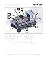
Page 15: ...r Control Panel 3 Composite Output Cable Trays 4 Fifth Wheel Assembly 5 Rear Axle Assembly 6 Emergency Stop Switch 7 Sliding Removable Canopy 8 Clearance Lights Option 9 Radiator End 10 Generator End 11 Forklift Pockets 12 Low Fuel Beacon Option 13 Operating Beacon Option Figure 1 1 1 General Assembly of Generator Set 2 3 4 1 5 6 7 8 9 11 10 13 3 12 ...

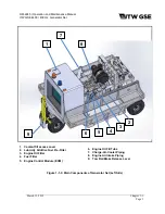
Page 16: ...Page 4 1 Cummins QSB4 5 Engine 2 Control Module Assembly 3 Batteries inside tray pockets 4 Battery Disconnect 5 Tow bar Assembly 6 Generator 7 28 5 VDC ARU Option 8 Engine Alternator 9 Output Contactors 10 Air Filter Assembly Figure 1 1 2 Main Components of Generator Set Right Side 1 2 3 10 6 8 7 5 9 4 ...

Page 17: ... 1 Coolant fill access cover 2 Lubricity Additive Fuel Pre Filter 3 Engine Oil Filter 4 Fuel Filter 5 Engine Control Module ECM 6 Engine Oil Fill Tube 7 Charge Air Cooler Piping 8 Engine Air Intake Piping 9 Tow Bar Brake Release Lever Figure 1 1 3 Main Components of Generator Set Left Side 1 2 3 4 5 7 8 9 6 ...

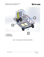
Page 18: ...peration and Maintenance Manual ITW GSE 4400 400 Hz Generator Set March 15 2015 Chapter 1 1 Page 6 1 Oil Drain Tube 2 Tie Down Rings 3 Muffler Assembly Figure 1 1 4 Main Components of Generator Set Bottom 1 2 3 ...

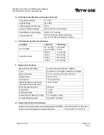
Page 19: ... Power factor 0 8 Duty Cycle 100 Operating speed 2000 RPM Overload capacity 125 rated load 325 Amps Output cable size 2 0 c AC Generator Protective System Specifications Condition Trip Point Time Delay Over voltage 130 volts 250 milliseconds 140 volts 15 milliseconds Under voltage any voltage below 104 volts 500 milliseconds Over frequency 380 Hz to 420 Hz 1 second above 480 Hz immediate Under fre...

Page 20: ...0 ms Output Overload 2000 A 5 seconds 1800 A 10 seconds 1200 A 30 seconds 800 A 30 seconds f Engine Specifications Manufacturer and Model Cummins Engine Company QSB4 5 Type 4 cylinder 4 cycle diesel electronic controlled Bore and Stroke 4 21 in x 4 88 in 107 mm x 124 mm Displacement 275 in 3 4 5 L Horsepower 171 hp 132 kW Idle speed factory set option Not authorized for EU units 1000 50 rpm Normal...

Page 21: ...control module that monitors records and controls engine performance d Battery System Disconnect Switch The generator set is equipped with a battery disconnect switch outside the unit on the RIGHT side The disconnect switch should be placed in the OFF position during long periods of shutdown 6 Canopy A composite enclosure identified as a canopy provides protection for the engine generator and elec...

Page 22: ...nic Control Module ECM The ECM is a pre programmed engine control module mounted directly to the engine block c Factory Installed Components and Protective Systems This generator set is assembled with the following components and protective systems 1 Shutdown Reset Systems x Emergency Shutdown The emergency shutdown switch is to provide instant manual shut off of the generator set by disconnecting...

Page 23: ...triction level is reached the circuit closes and the air cleaner indicator fault appears on the control panel fault display to warn the operator that the air cleaner must be changed The electrical indicator automatically resets when the restriction level drops sufficiently Note This function should not be used as a replacement indicator Follow recommended replacement schedule as specified in this ...

Page 24: ...or revolving fields The exciter outputs DC to the generator fields and consequently the generator output is controlled by the voltage regulator PC board REG A centrifugal radial blade fan draws cooling air over all internal windings Air enters at the exciter end and is discharged at the drive end The complete generator assembly is bolted to the engine s flywheel and housing 8 Operator Controls The...

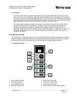
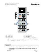
Page 25: ... OFF buttons are used to turn on and off their respective outputs If a specific output has a fault the corresponding ON OFF button will also reset that fault 8 The power ON Engine Start Stop button will wake the unit from low power sleep mode Pressing it again will begin the start up sequence for the diesel engine Pressing it again will shut down the engine If the engine is already running it will...

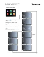
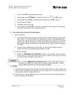
Page 26: ...will only be displayed if that option is available Pressing Ż will return to the default menu screen Unit information is displayed using the information icon To access the information icon press the To enter the Icon Menu press the Ɣ from the default menu and hold it down for approximately 5 seconds To Select a submenu simply use the navigation keys ŻźŸŹ to highlight the icon and then press the Ɣ ...

Page 27: ...OM 2245 Operation and Maintenance Manual ITW GSE 4400 400 Hz Generator Set March 15 2015 Chapter 1 1 Page 15 March 15 2015 Chapte ...

Page 28: ...ter and overload circuit 1 Line Drop Compensation The current transformers detect the magnitude and power factor of current flowing from generator to load They feed a signal to the voltage regulator that interprets the signal and alters the exciter field current as required to maintain a constant predetermined voltage at the load These values are accessible on the color display 2 Ammeter The curre...

Page 29: ...start The intake air heater or grid heater is energized or de energized from a power relay controlled by the ECM The amount of time the air intake heaters stay on in the preheat phase is a function of the intake manifold temperature at start up The pre heat time increases with colder intake manifold temperatures The maximum duration of the pre heat phase is around 30 seconds CAUTION Never use an e...

Page 30: ... and 28 VDC outputs and cannot exceed units 400 Hz power rating Figure 1 1 7 ARU Front view Figure 1 1 8 ARU Rear View Input Contactor Q3 The 400 Hz input power to the ARU is supplied and controlled via Q3 Supply Module G20 The generation of the 24 VDC 10 A Adjusted from factory 25 Volt regulated control voltage is done by the Supply Module G20 This module has a wide input range 340 575 VAC It is ...

Page 31: ...e unit is turned off Filter Capacitor C20 The output filter capacitor is part of the output filter stage and ensures that the AC ripple is kept to a minimum less than 2 at the output Fan M20 The fan M20 is part of the total forced cooling of the unit the primary task for the fan is to cool down the rectifier module The air is blown out via the filter grill on the left hand side of the base module ...

Page 32: ...tightening hose clamps tube fitting etc as required 5 Check tightness of the generator set retaining components 6 Check the fuel level A manual quick reference fuel gauge is located at the back of the unit NOTE For recommended fuel specifications refer to the Engine Manufacturers Operation and Maintenance Manual provided with this manual 7 Check the engine coolant Remove the radiator cap under the...

Page 33: ...igh mark as possible without going over it See Figure 1 2 1 for capacity CAUTION NEVER operate the engine with oil level below the L level mark or above the H level mark NOTE See the Engine Manufacturer s Operation Maintenance Manual for oil recommendations Figure 1 2 2 Oil Fill and Oil Level Check Locations 9 Check the batteries which are located in the right side cable tray Inspect the batteries...

Page 34: ...nto a double ferrule and then inserted into the normally open auxiliary contact block attached to the side of the output contactor See Figure 1 2 5 To install AC output cables proceed as follows 1 Remove the canopy While this may not be necessary it greatly simplifies the process 2 Loosen the screws on the cable clamps 3 Route the cables through the hole in the cable tray and then through the cabl...

Page 35: ...rocess 2 The DC output cable is not normally supplied unless specifically ordered For normal aircraft service use cable assembly JB2840 30 which meets Mil C 7974D Assembly specification with 30 feet of AWG 4 0 cables having a positive and negative connection 3 The output cable is extended through the frame via the supplied hole in the cable tray See Figure 1 2 3 4 The cables will be connected to t...

Page 36: ...absorbing chemicals are to be effective b Temporary Storage When storing the unit for 30 days or less prepare as follows 1 Lubricate the unit completely in accordance with instructions in Section 2 2 This will include changing engine oil and all filter elements 2 Start the engine and operate for a minimum of two minutes so that all internal engine components will be coated with new oil Note if the...

Page 37: ...tion before starting the engine 2 Start the engine and operate under full load using a resistive load bank or aircraft until the coolant temperature has reached at least 176ºF 80ºC 3 While the engine is running ensure that normal operating controls are in good working condition before shutdown and storage If weekly operation is not possible contact the nearest engine manufacturer distributor for i...

Page 38: ...oil and coolant in the engine iv Be sure that the battery isolation switch is closed ensuring that 24 VDC power is available to the engine starting and control systems v Make certain the control panel is on If not press the Power ON Engine Start Stop button to wake the unit b Normal Engine Starting Procedures CAUTION Refer to operating instructions in the engine manufacturer s operation manual whe...

Page 39: ... 7 Output ON OFF Reset 8 Power ON Engine Start Stop Reset All output and engine buttons are multitasking buttons dependent upon the current status of the unit The displayed screen is NOT important These buttons are always active CAUTION Never use an ether start system in conjunction with the air intake heater ii Check oil pressure to make certain that it is normal and observe all other engine valu...

Page 40: ...ush buttons to view either the line to line or line to neutral voltage If the load is changing observe the display until load conditions stabilize iii A condition of over voltage under voltage under frequency over frequency or overload in the output circuit will automatically open the load contactor and display a fault code to signal the operator which of the above faults caused the protective mon...

Page 41: ...ill remain active If idle is enabled the generator will deactivate and the engine will return to idle after a short delay b Push the engine Start Stop push button switch once to begin the automatic shutdown sequence to shut off the engine after approximately 5 minutes ii Emergency conditions 1 Depress the EMERGENCY STOP BUTTON located on the front of the unit to the right of the control panel When...

Page 42: ...28V Current Limit menu item and press Ɣ twice ii Use the up or down arrow buttons to change the default value to the desired current limit for the aircraft being powered iii Press Ɣ to accept the changed value as the new default value b If the current limit only needs to be changed for a one time use use the following procedure i With the unit s engine running and the 28 VDC power is off the right...

Page 43: ... will not function if the plug not is fully inserted b Press the 28 VDC Start Stop button c The unit is now in operation and supplying power to the aircraft This is also indicated via the green LED located close to the 28VDC Start Stop button d If the unit shuts off and is no longer supplying power to the aircraft this is reported in clear text in the display Also a corrective action is displayed ...

Page 44: ...note that the 28 VDC Start Stop button also functions as a Reset push button If for some reason the unit stops due to an error failure record the fault number and message and forward this information to your maintenance personnel If the fault is no longer active press the Start Stop Reset to reset the alarm and the unit 3 ARU Default Factory Settings 28 V Voltage V 28 0 28 V Compensation V 600A 0 ...

Page 45: ...00 400 Hz Generator Set March 15 2015 Chapter 1 3 Page 8 Center navigation Button 4 0 Icon Menu The Icon Menu is accessed from the Default screen Press the center navigation button Ɣ while in the default menu and hold it down for approximately 5 seconds ...

Page 46: ...apter 1 3 Page 9 4 0 1 View Parameters Menu The View Parameters Menu is accessed from the Icon screen Press the center navigation button Ɣ while in the default menu and hold it down for approximately 5 seconds The Icon menu is displayed press the right navigation button to highlight the icon ...

Page 47: ...2015 Chapter 1 3 Page 10 4 0 2 Setup Menu The Setup Menu is accessed from the Icon screen Press the center navigation button Ɣ while in the default menu and hold it down for approximately 5 seconds The Icon menu is displayed press the right navigation button to highlight the Setup icon ...

Page 48: ...OM 2245 Operation and Maintenance Manual ITW GSE 4400 400 Hz Generator Set March 15 2015 Chapter 1 3 Page 11 ...

Page 49: ...OM 2245 Operation and Maintenance Manual ITW GSE 4400 400 Hz Generator Set March 15 2015 Chapter 1 3 Page 12 ...

Page 50: ...OM 2245 Operation and Maintenance Manual ITW GSE 4400 400 Hz Generator Set March 15 2015 Chapter 1 3 Page 13 ...

Page 51: ... the compensation using the vertical arrow buttons until the voltage at the aircraft connector equals the no load value Press FHQWHU Ɣ EXWWRQ to accept and record this value Press the LEFT arrow button to exit the submenu and return to the submenu list 4 3 Output 2 Compensation The output voltage is increased in proportion to the load current Volt 100 A 1 Apply full load to output 2 2 Enter the OU...

Page 52: ... reset to Active if the unit detects 28 volts on the F pin input of the I O board Go into the Setup Menu and then scroll up or down to the 28V Interlock submenu Press the centHU Ɣ EXWWRQ WR HQWHU WKH VXEPHQX DQG WKHQ SUHVV WKH Ɣ EXWWRQ DJDLQ WR DOORZ WKH YDOXH WR EH FKDQJHG 3UHVV WKH XS RU GRZQ DUURZ EXWWRQV WR FKDQJH WKH VHOHFWLRQ 3UHVV WKH FHQWHU Ɣ EXWWRQ WR UHFRUG WKH QHZ YDOXH Press the LEFT a...

Page 53: ...y Opened or Normally Closed temperature sensor switches to be used R LQWR WKH 6HWXS 0HQX DQG WKHQ VFUROO XS RU GRZQ WR WKH 3OXJ 7HPSHUDWXUH VXEPHQX 3UHVV WKH FHQWHU Ɣ EXWWRQ WR HQWHU WKH VXEPHQX DQG WKHQ SUHVV WKH Ɣ EXWWRQ DJDLQ WR DOlow the value to be changed Press WKH XS RU GRZQ DUURZ EXWWRQV WR FKDQJH WKH VHOHFWLRQ 3UHVV WKH FHQWHU Ɣ EXWWRQ WR UHFRUG WKH QHZ YDOXH Press the LEFT arrow button t...

Page 54: ...WR FKDQJH WKH VHOHFWLRQ 3UHVV WKH FHQWHU Ɣ EXWWRQ WR UHFRUG the new value Press the LEFT arrow button to exit the submenu and return to the submenu list 4 14 LED Brightness The unit status LED s have three brightness levels The default is set to medium R LQWR WKH 6HWXS 0HQX DQG WKHQ VFUROO XS RU GRZQ WR WKH ULJKWQHVV VXEPHQX 3UHVV WKH FHQWHU Ɣ EXWWRQ WR HQWHU WKH VXEPHQX DQG WKHQ SUHVV WKH Ɣ EXWWR...

Page 55: ...um output voltage of the unit is 33 VDC QWHU WKH 6HWXS 0HQX DQG WKHQ VFUROO XS RU GRZQ WR WKH 9 RPSHQVDWLRQ VXEPHQX 3UHVV WKH FHQWHU Ɣ EXWWRQ WR HQWHU WKH VXEPHQX DQG WKHQ SUHVV WKH Ɣ EXWWRQ DJDLQ WR DOORZ WKH YDOXH WR EH FKDQJHG 3UHVV the up or down arrow buttons to change the selection 3UHVV WKH FHQWHU Ɣ EXWWRQ WR UHFRUG WKH QHZ YDOXH Press the LEFT arrow button to exit the submenu and return to...

Page 56: ...WHU Ɣ EXWWRQ WR UHFRUG WKH QHZ YDOXH Press the LEFT arrow button to exit the submenu and return to the submenu list 4 21 Language This submenu is used to change the language that all of the display screens messages alarms and reports are displayed in The unit comes with Danish English German French and Spanish already installed The default is set to English R LQWR WKH 6HWXS 0HQX DQG WKHQ VFUROO XS...

Page 57: ...15 Chapter 1 3 Page 20 4 0 3 Black Box The Black Box Menu is accessed from the Icon screen Press the center navigation button Ɣ while in the default menu and hold it down for approximately 5 seconds The Icon menu is displayed press the right navigation button to highlight the Setup icon ...

Page 58: ...15 Chapter 1 3 Page 21 4 0 4 Power Log The Power Log Menu is accessed from the Icon screen Press the center navigation button Ɣ while in the default menu and hold it down for approximately 5 seconds The Icon menu is displayed press the right navigation button to highlight the Setup icon ...

Page 59: ...er 1 3 Page 22 4 0 5 Upload Download Menu The Upload Download Menu is accessed from the Icon screen Press the center navigation button Ɣ while in the default menu and hold it down for approximately 5 seconds The Icon menu is displayed press the right navigation button to highlight the Setup icon ...

Page 60: ...OM 2245 Operation and Maintenance Manual ITW GSE 4400 400 Hz Generator Set March 15 2015 Chapter 1 3 Page 23 ...

Page 61: ...OM 2245 Operation and Maintenance Manual ITW GSE 4400 400 Hz Generator Set March 15 2015 Chapter 1 3 Page 24 ...

Page 62: ...schedule check sheet such as the one in the engine manufacture s operation manual The check sheet will provide a record and serve as a guide for establishment of a schedule to meet the customer s maintenance requirements for his specific operation c Time Intervals The schedule is based on both hours of operation and calendar intervals These two intervals are not necessarily the same For example in...

Page 63: ...heck Exhaust System X X Charge Air Cooler CAC and Piping X Change Lubricity Fuel Filter Element X X Check Radiator Core and Hoses X Check Oil Pressure and Record X Change Crankcase Oil X X Change Oil Filter Element X X Check Engine and Generator Mounts X X Check Coolant Additive Concentration X X Check Fan Hub and Drive Pulley X Check Hose Clamps on Air Intake Side X X Check Belt Conditions and Te...

Page 64: ...heck Thermostats and Seals Fall Electrical 24 VDC System Check All Lights X Check Alternator Charging Rate X Check Battery X Clean Battery Terminals X X Check Wiring and Connections X Check All Engine Meters X Electrical 400 Hz System Check E F By Pass Operation X Check Output Cable and Connectors X Check Volt Amp Frequency Displays X Check and or Adjust Output Voltage X X Inspect Wiring and Conne...

Page 65: ...hrs The following procedures are precautionary measures taken on most new engines If a problem occurs with any of the following issues be sure to recheck it after the next 50 150 hours 1 Engine a Check for leaks and correct This involves an overall inspection of the engine and may require some maintenance if leaks are found Refer to the engine manufacturer s operations manual for assistance b Chan...

Page 66: ...TION BE SURE to prime and bleed the fuel system after draining the filters replacing filter element or if the fuel tank has run empty Failure to do so can cause engine starting problems i Provide a container for catching drained fuel ii Open the drain valve on the fuel water filter by turning it counterclockwise iii Drain the filter until clear fuel is visible iv Tighten the drain valve v Safely d...

Page 67: ...leaking and defective exhaust system could be a fire hazard 2 Electrical System 24 VDC a Check All Lights Check all indicating lights to be sure they operate when they should If any light fails to operate check the indicator and insure proper power is being given If power is present and the light does not activate replace the light fixture b Check Engine Battery Voltage Observe the engine voltmete...

Page 68: ...emperature for complete combustion of fuel and will also increase the fuel consumption rate The unburned fuel collects in the exhaust system to create the wet condition known as wet stacking To alleviate wet stacking in lightly loaded engines it is recommended that the machine be connected to a load bank after each 250 hours of use and operated under full rated load for one hour This will burn awa...

Page 69: ...ks and Operations 500 Hours or 6 Months 1 Engine a Check Engine and Generator Mounts CAUTION An unstable or loosely mounted engine can create hazardous environment and may damage equipment i Engine mount bolts must be torqued to 100 N m 73 7 ft lb ii Generator mount bolts must be torqued to 100 N m 73 7 ft lb b Change oil and oil filters c Change all fuel filters d Check Coolant Additive Concentra...

Page 70: ... worn features Tighten bolts and replace parts if necessary Refer to the engine manufacturer s operations and maintenance manual for assistance and the most update to date information b Check Hose Clamps on Air Intake Side Be sure that all clamps are properly secured to prevent leaks and all hose are in good condition c Check Belt Condition and Tensioner Refer to the engine manufacturer s operatio...

Page 71: ...d engine however there are some CAUTIONS to be observed WARNING Exercise care to avoid injury and damage to eyes and skin CAUTION 1 If a cleaning compound is used select one that is free from acid and will not remove paint 2 Protect or remove all electrical accessories such as voltage regulator alternator and electrical wiring 3 Seal all openings DO NOT use a flammable solvent 4 DO NOT use mineral...

Page 72: ...es Check vibration damper for looseness wobble chunking and streaking Also verify the hub bolts are tightened to the engine manufacturer s specifications Refer to the engine manufacturer s operations and maintenance manual for assistance and the most update to date information b Check Charge Air Cooler and Radiator Systems i Check for damaged hoses and loose or damaged hose clamps ii Check the rad...

Page 73: ...fan hub and crankshaft pulley for secure mounting 2 Check cooling system each spring and fall Clean if necessary 3 Check All Hoses In addition to daily checks of hoses for leaks inspect hoses thoroughly each time the cooling system is cleaned and serviced Inspect for signs of deterioration and collapse Inspect for cracks and cuts Inspect for cutting and deformation caused by hose clamps Replace ho...

Page 74: ...ed Location Schematic Type Identifier Display Board Interface Board F1 2A Control Board Interface Board F2 5A Exciter Circuit 24V Interface Board F3 5A Contactors Interface Board F4 5A Relays Interface Board F5 2A Key Switch Interface Board F6 5A ECM Dongle Interface Board F7 5A Exciter Circuit 180 V Interface Board F8 500V 6 3A ECM Interface Board F9 20A Engine Air Intake Heater Engine Electrical...
Page 75: ...in coolant system according to Section 2 2 paragraph 6 Engine coolant capacity is approximately 20 quarts 18 9 liters Coolant hoses and connections Check coolant hoses and connections daily for leaks Air Cleaner Change air cleaner filter as required when the fault code display on engine control panel shows the Air code Fan Belt Check fan belt condition and tension every 1000 hours or 1 year of use...

Page 76: ...Oil specification The engine lubricating oil that is recommended by the engine manufacturer is identified by an API American Petroleum Institute classification designation The manufacturer does not recommend any specific brand of lubricating oil The use of quality lubricating oil combined with appropriate lubricating oil drain and filter change intervals are important factors in extending engine l...

Page 77: ...ge engine oil is soon after a power delivery run when the engine is at operating temperature If lubricating oil is drained immediately after the unit has been run for some time most of the sediment will be in suspension and will drain readily Change the oil filter element each time the oil is changed CAUTION x High ash oils may produce harmful deposits on valves that can cause valve burning x Do n...

Page 78: ...y a light coating of lubricating oil to the gasket sealing surface and install the filter DO NOT over tighten the filter 10 Clean the drain cap and install when engine oil has completely drained 11 Refill the engine with new clean oil that meets engine manufacturer s recommendations Use the oil fill tube by the filter or the oil fill opening at the top of the engine CAUTION Remember to close the d...

Page 79: ... motors are lubricated at assembly and should be re lubricated only when the starter is removed and disassembled however inspect the starter to make certain it has no lubrication points 3 Water Pump The water pump is packed at assembly and requires no periodic lubrication Replace pump if signs of lubricant leakage are found 4 Fan Pulley The fan hub is also lubricated at assembly and requires no pe...

Page 80: ...Replace when the Air Filter Clogged warning appears on the display Figure 2 2 3 Air Cleaner Assembly Inspecting the Air Cleaner 1 Make periodic checks of air cleaner inlet screen for obstructions If any obstructions are present remove them 2 Check outlet connection for proper seal b Changing the Air Filter 1 Pull out the latch and rotate the back cover to the unlocked position counterclockwise as ...

Page 81: ...higher than 0 5 oil change intervals should be reduced See engine manufacturer s operation manual In general fuels meeting the properties of ASTM designation D 975 grades 1 D and 2 D have provided satisfactory performance For more information regarding the selection of fuel to use refer to publication Engine Requirements Lubricating Oil Fuel and Filters available from authorized engine maker s ser...

Page 82: ...s mounted in the generator compartment above the fuel tank outlet The filter s function is to add a lubricant to the fuel to help prolong the engine seals and fuel pump life when fuels other than diesel are used i e jet fuel The filter also removes foreign material and removes both free and emulsified water from the fuel before it enters the fuel lift pump Daily draining of the filter is required ...

Page 83: ...ted correctly against the gasket and tighten with a final half turn 10 Make sure that all rags or absorbent sheets are clear of moving engine parts and cannot be drawn in to the radiator fan 11 Open fuel valve 12 Start the engine and check for leaks Correct as necessary with the engine off c Primary Fuel Filter A primary fuel filter is mounted above the engine starter in the engine compartment The...

Page 84: ... and cannot be drawn in to the radiator fan 7 Fill new filter with diesel fuel Screw in the new fuel filter snug Check that the cartridge is seated correctly against the gasket and tighten with a final half turn 8 Open fuel valve d Fuel Pump The fuel pump supplies high pressure to the fuel system so the diesel fuel can circulate freely This engine is equipped with a common rail fuel system that is...

Page 85: ...pen at a pressure of approximately 15 psi 103 4 Kpa WARNING When removing cap from a very hot radiator do not turn cap past safety stop until the pressure or steam has escaped 2 Removal To remove turn the cap to the left counterclockwise to the safety stop When all pressure is released press down on the cap and continue to turn until the cap is free to be removed CAUTION Allow engine to cool befor...

Page 86: ...ster when in doubt about antifreeze protection d Draining the Cooling System To completely empty the cooling system requires draining the engine block if furnished and the radiator assembly Both drain valves radiator and block drain can be opened closed at the same time but they do not need to be Follow these steps to drain the cooling system 1 Remove radiator cap 2 Place a drain pan with at least...

Page 87: ...th radiator drain valves are closed b Pour coolant into radiator very slowly until it reaches the bottom of fill neck Allow time for trapped air to escape from the system then continue filling until the coolant level remains at the bottom of the fill neck c Start the engine and bring up to rated speed and allow the thermostat to open Add coolant as trapped air escapes from the system and the coola...

Page 88: ...elt tension may be checked by hand To do so manually depress the belt with an index finger to determine the amount of belt deflection obtained When a force is applied at a point halfway between pulleys on the longest span of a belt there should be no more than 1 2 inch of deflection attained Refer to the engine manufacturer s operation manual for checking belt tension and changing worn belts 8 Gen...

Page 89: ...reventative maintenance to the ground power unit Generator Set Model Number Make sure your generator set is the model listed above Identify the model number by looking on the data plate which is located on the frame at the front right corner of the unit Filter Part Numbers The table below lists the filter part numbers for your generator set Filter ITW GSE Part Number Oil Filter Element 3937736 Eng...

Page 90: ...of parts Our helpful parts staff is also able to provide delivery information for the customer Contact the ITW GSE parts department staff for all the preventative maintenance parts e mail parts itwgse us call inside USA 866 845 0441 call other countries 941 721 1000 For more information about maintenance procedures refer to Chapter 2 of the manual Filter Pictures Air Cleaner Oil Filter Fuel Filter...

Page 91: ...glycol and water Total capacity is 20 quarts 3 Check tension of drive belt 4 Verify that there is at least tank of diesel fuel 5 Make a general inspection of all wiring and terminals Inspect the equipment to be certain no damage will result from starting the engine 6 Turn on battery disconnect switch 7 Place unit in Engine Only Diagnostic Mode See Menu Operating Instructions Chapter 1 3 Paragraph ...

Page 92: ... engine button to shut down unit 9 Disable Diagnostic Mode d 400Hz Initial Testing and Setup 1 Connect Output cable s to the appropriate load bank s with interlock enabled as required 2 Press engine button to start engine Engine should go straight to rated speed 3 Verify Output frequency on power analyzer 400Hz 2Hz Measured Frequency __________Hz 4 Verify Output voltage line to N 5 MEASURED Voltag...

Page 93: ...the engine button h Re checking the entire unit after testing 1 Start the engine With the engine running at normal rated speed check the entire unit for vibration and for any parts that may have become loosened during the above checks Tighten any loose hardware as required 2 Check engine oil pressure at rated speed 2000 RPM The oil pressure gauge should indicate at least 44 9 psi 3 1 bar when engi...

Page 94: ...argest available three phase load of rated power factor not exceeding the maximum rating of the generator set i e 72 kW for a 90 kVA at 0 8 pf generator ii Measure the output voltage at the load end of the cables as you increase the load from zero to the maximum full load rating of the unit If the voltage at the end of the cable rises or drops more than 1 decrease or increase the line drop compens...

Page 95: ... leads at the back of the unit b Disconnect the two black exciter field leads Connector J6 P6 that is located under the back right corner of the unit c Check resistance and compare to values Test Connection Resistance Ohms Generator Stator Phase A to N G1 0 0026 Generator Stator Phase B to N G1 0 0026 Generator Stator Phase C to N G1 0 0026 Exciter Stator Field L2 29 A B B C C A Exciter Armature G...

Page 96: ... diode may be considered good 6 Testing the Active Rectifier Unit ARU for units with the DC option The 28 5 VDC ARU is an optional add on to the GPU The following test procedures may be used for testing the ARU following repair or for just checking performance a Preparation for Testing 1 Connect the ARU to a DC load bank 2 Start the GPU per the operating procedures in Chapter 1 Section 3 b Operati...

Page 97: ...0 amps to 2400 amps for the 600 amp version a Start the diesel engine b Once the engine has stabilized at its running speed use the Right or Left navigation buttons to set the current limit to 1400 amps c Press the 28VDC pushbutton to close the contactor to apply the load to the load bank d Press the Engine Test switch on the load bank Verify that the current never exceeds 1400 amps e Press 28 VDC...

Page 98: ...OM 2245 Operation and Maintenance Manual ITW GSE 4400 400 Hz Generator Set This page is intentionally left blank ...

Page 99: ...per leads Damage to electrical components may result from the application of improper voltage and current 2 Equipment for Troubleshooting A good quality multimeter is the only instrument required for troubleshooting At least two jumper leads with alligator or similar clips will be required The engine electrical system may be used as a 24 VDC power source 3 Parts Replacement To lessen end item down...

Page 100: ...nostics of the internal circuitry If a fault is detected during the self test the Alert Failure LED will be lit and the first if there are more than one failure will be displayed on the LED display 2 Engine Run Mode When the ENGINE pushbutton is activated the engine s starter and the engine s ECM will be energized After the engine reaches its rated speed 2000 rpm the GPU is ready to supply power t...

Page 101: ...ay Pressing the Engine pushbutton or shutting down the GPU resets the fault 8 Cummins Engine Fault Codes Trouble Shooting The best source of information to aid in trouble shooting Cummins engine issues is at the quickserve cummins com website Go to this website and register up to five engine serial numbers for free It is recommended that if you have more than one engine type size that you register...

Page 102: ...the aircraft on output 2 is beyond the defined limit Press Output 2 button to reset 2200 PLUG 1 TEMPERATURE TOO HIGH The temperature sensor in output 1 plug has tripped Press Output 1 button to reset 2300 PLUG 2 TEMPERATURE TOO HIGH The temperature sensor in output 2 plug has tripped Press Output 2 button to reset 2400 28V PLUG TEMPERATURE TOO HIGH The temperature sensor in output 2 plug has tripp...

Page 103: ...ut cabling Replace Control Boards A1 A2 2200 Remove load and let plug cool down Check connector output cabling for any malfunction Replace Control Boards A1 A2 2300 Remove load and let plug cool down Check connector output cabling for any malfunction Replace Control Boards A1 A2 2400 Remove load and let plug cool down Check connector output cabling for any malfunction Replace Control Boards A1 A2 ...

Page 104: ...pacity jumper cable No 1 0 minimum between the hot side of the starter solenoid and the starter input terminal If starter does not crank engine the starter may be defective e No voltage at starter solenoid coil x Check connector X5 on the PC1 Interface board x Verify that there is 24 VDC across the starter solenoid and terminals when the engine start pushbutton is pressed x Check and replace if ne...

Page 105: ...ections Replace any damaged hoses or fuel links 5 Engine cranks but will not start Over temperature indication appears immediately a Defective engine temperature switch Check wiring to engine high temperature switch S49 on schematic which is located on top of the engine block If wiring is correct remove wires and check resistance between terminals C and N O A resistance of less than 10 ohms indica...

Page 106: ...eration manual d Air in fuel system Check all fittings to be sure they are tight and the thread sealant is still present Tighten the fittings and add new thread sealant as required 11 Engine lacks power a Improper engine adjustments and gear train timing Tune up engine in accordance with engine manufacturer s operation manual b Insufficient fuel Check low fuel level in accordance with engine manuf...

Page 107: ...o AVR Battery Only This applies 24 VDC from the battery to the exciter field which should produce an indicated output voltage of 100 20 VAC line to neutral b Verify 24 VDC across connector J6 terminals A B Check X20 on the Interface board and connector J6 at the generator c Defective connector at voltage regulator or defective wiring from regulator to exciter field Disconnect the exciter wires at ...

Page 108: ...hase a Open or short circuited winding in generator stator G1 Check stator winding resistances See Chapter 2 3 Section 4 for normal values 3 Generator overheats a Loose connection causing high resistance Check all output connections Look for discoloration caused by heat Tighten or replace as required b Improper or blocked ventilation Check for foreign material rags etc blocking airflow Provide ade...

Page 109: ...Cause Test Check and or Remedy 1 Load contactor will not close when the corresponding Output pushbutton is pressed Generator is running at normal voltage a Blown contactor fuse F3 on regulator board Check the fuse and replace if blown If it blows again check the contactor b Defective display module Check to make sure that the other pushbuttons on the control panel work Replace the display board an...

Page 110: ...the plug interlock EF circuit from aircraft for following reasons Proceed as follows to find the cause of this malfunction c Generator to aircraft cable connector defective or not plugged into aircraft receptacle connector Inspect cable connector plug thoroughly for damaged E and F terminals Be sure plug is fully mated with aircraft receptacle connector and making good contact d Aircraft rejecting...

Page 111: ...ep b b Defective Interface or control board With load bank at no load use the Output Voltage screen in the Setup menu Chapter 1 3 Paragraph 4 1 to reduce the voltage to 110 VAC Observe the voltmeter on the load bank and gradually increase voltage If the load contactor opens at any value less than 125 VAC replace the interface and processor board 2 Load contactor opens during power delivery Under v...

Page 112: ...OM 2245 Operation and Maintenance Manual ITW GSE 4400 400 Hz Generator Set This page is intentionally left blank ...

Page 113: ...iter and rear main bearing can be removed without removing the generator from the generator set The name exciter armature refers to the shaft mounted revolving three phase windings of the exciter 1 Coupling Key Not Shown 2 Flex Coupling Assembly 3 Generator Housing Stator Assembly 4 Armature Assembly 5 Exciter Housing Coils Assembly 6 Exciter Cover 7 Exciter Armature Assembly Not Shown 8 Exciter K...

Page 114: ...ng replacement The exciter armature has two M10 1 5 tapped holes in its diode mounting plate to accommodate pulling it off the shaft Since the removal and installation of exciter armatures can be rather complicated this manual has been prepared to assist mechanics in the operation It may be necessary to remove the exciter armature several times for bearing replacement during the life of a generato...

Page 115: ... for fabricating such a tool Sling hammer pullers are also commercially available Instructions for using tool are provided in this manual Once the threaded machine key is removed No other special tools are required for removing the exciter from the generator shaft This can be done using the two M10 1 5 fully threaded hex head bolts Instructions for doing this are provided in this manual c Conditio...

Page 116: ...into key until stud bottoms in key threads Tighten securely b If hammer 5 and rod 4 are not already assembled thread one nut 3 onto adapter end of rod 4 Thread rod into adapter until it bottoms then tighten nut securely against adapter Slide hammer 5 onto rod and install washer 6 and two nuts 3 Thread nuts onto rod until both nuts are full threaded and locked together WARNING Be very careful durin...

Page 117: ...o M10 1 5 hex head bolts as shown in Figure 3 1 4 to force the exciter armature off the shaft Turn each of the two screws a few turns at a time into the threaded holes of the diode mounting plate until the exciter armature is sufficiently loosened from the shaft to be removed from it by hand Remove it slowly from the shaft and at the same time observe the following CAUTION 1 Stud 1 4 28 UNF 2A Gra...

Page 118: ...le Figure 3 1 2 Straighten leads and remove kinks as required to avoid damage to insulation 4 Exciter Armature Installation a Preparation for Exciter Armature Installation 1 Clean generator shaft and exciter armature bore Remove all rust corrosion etc 2 Make CERTAIN that the leads are tucked into the 1 2 keyway which is opposite from the 3 8 keyway in the generator armature shaft Figure 3 1 4 Exci...

Page 119: ... the hole Figure 3 1 2 in the diode mounting plate Screw the nut onto the bolt until it is near the head of the bolt Insert the bolt through the hole in the center of the diode mounting plate as far as it will go and screw it into the end of the armature shaft Screw the nut up against the diode mounting plate Continue turning the nut until the diode mounting plate contacts the end of the generator...

Page 120: ...haft and armature bore is NOT recommended because there is a danger that it may mix with and contaminate the LOCTITE Application of NEVER SEEZ will be at the customer s risk LOCTITE can lose its adhesive and tightening properties if contaminated by rust preventatives oil or other lubricants and antirust products Recommended Products Manufacturers x Locquic No 47 56 Primer Grade T x Loctite No 40 3...

Page 121: ...between the engine and the generator due to manufacturing tolerances A tapered bushing and hub secures the coupling to the generator shaft Figure 3 2 1 Coupling Assembly 2 Disassembly Removal of the flexible coupling is required for servicing the generator armature generator bearings or the coupling itself To remove the coupling for any reason it is necessary to separate the engine and generator H...

Page 122: ...eparate the bushing from the hub lubricate two of the 3 8 16 bolts and insert them into the two threaded holes in the bushing flange With socket wrench screw these bolts into the bushing such that the bushing pops loose from the hub alternating from bolt to bolt 4 When the bushing is loose in the hub use a mallet to GENTLY tap the bushing out of the hub 5 Slide the coupling assembly off the shaft ...

Page 123: ...r any damage or deformation where the coupling was mounted on it e Check rubber bushing alignment to make sure that the dimension illustrated in Figure 3 2 4 is maintained 1 Bolt 3 8 16 UNC 3 2 Taper Lock Bushing 3 Taper Lock Hub 4 Tapped holes 2 5 Key 6 Set Screw 7 Fan Coupling Disk 8 Armature Shaft Figure 3 2 3 Hub and Bushing ...

Page 124: ...ign Countries 941 721 1091 E Mail technicalsupport itwgse us parts itwgse us Web Page www itwgse com a Replacement Coupling Kit A replacement coupling kit is available from ITW GSE The kit provides a replacement coupling assembly with attaching hardware and installation instructions b Bushing Kit A bushing kit is available from ITW GSE for replacing the rubber bushing only in the coupling assembly...

Page 125: ...side of the hub be thoroughly CLEANED FREE OF DIRT AND GRIT CAUTION Do not lubricate any of the surfaces listed above Lubrication of these surfaces can cause the coupling to fail and damage the generator set Slight traces of rust are permissible on the surfaces b Assembly 1 If an adapter ring must be replaced remove the bolts that secure it to the flywheel Discard the old adapter ring and bolts In...

Page 126: ... 10 Tighten the 3 8 16 bolts alternately and evenly as follows a Set a torque wrench to 30 foot pounds 41 N m and tighten all three 3 8 16 bolts to that value Block the coupling against clockwise rotation with a bar as illustrated in Figure 3 2 2 Observe the CAUTION above when it is necessary to rotate the shaft b Repeat step a above until 3 8 16 bolts can no longer be tightened c Recheck the dime...

Page 127: ...a and operate it for a 2 hour run in b Shut down the engine after 2 hours and re torque all coupling bolts to 85 foot pounds 115 N m to compensate for normal torque relaxation c Return the unit to normal service d After 200 hours of operation check all coupling bolts with a torque wrench set at 85 foot pounds 115 N m e Return the unit to normal service f After each additional 2 000 hours of operat...

Page 128: ...OM 2245 Operation and Maintenance Manual ITW GSE 4400 400 Hz Generator Set March 15 2015 Chapter 3 2 Page 8 Figure 3 2 4 Bushing Installation ...

Page 129: ...OM 2245 Operation and Maintenance Manual ITW GSE 4400 400 Hz Generator Set March 15 2015 Chapter 3 2 Page 9 Figure 3 2 5 Assembly Procedure Figure 3 2 6 Measure from mounting face to adapter ring ...

Page 130: ...OM 2245 Operation and Maintenance Manual ITW GSE 4400 400 Hz Generator Set March 15 2015 Chapter 3 2 Page 10 Figure 3 2 7 Measuring From Mounting Face To Bushing ...

Page 131: ... of the control box and remove the control box 5 Remove the air cleaner and the pipe hoses connecting it to the engine Note cover the turbo inlet while the air cleaner is removed 6 Remove the generator stator leads from the power module and remove the power module 7 Remove required support table components above the generator 8 Remove generator housing cover b Removing the Generator Assembly 1 Rem...

Page 132: ...heel housing with wooden blocks or second hoist if available 2 Using the hoist support the generator assembly and lower it carefully and slowly into position for attachment to the engine 3 While still supporting the generator assembly with the hoist attach the generator housing to the engine using the bolts removed earlier Torque bolts to 30 ft lb 41 N m 4 Attach the flywheel coupling to the engin...

Page 133: ...cept Standard hardware items attaching parts such as nuts screws washers etc which are available commercially Bulk items such as wire cable sleeving tubing etc which are also commercially available Permanently attached parts which lose their identity by being welded soldered riveted etc to other parts weldments or assemblies b Parts List Form This form is divided into six columns Beginning at the ...

Page 134: ...onents of an assembly are listed directly below the assembly and indented one space Vendor codes and part numbers for purchased parts are also listed in this column when applicable Hobart modification to vendor items is also noted in this column 4 EFF Effective Column This column is used to indicate the applicability of parts to different models of equipment When more than one model of equipment i...

Page 135: ...t DIA Diameter Deg Degree Fig Figure hd Head hex Hexagon Hz Hertz cycles per second ID Inside diameter IN Inch kVA Kilovolt ampere lg Long uF Microfarad No Number Not supplied by Hobart No Number NHA Next higher assembly OD Outside Diameter PRV Peak reverse voltage PSI Pounds per square inch Ref Reference the item has been listed previously RH Right Hand LH Left Hand TM Technical Manual T R Transf...

Page 136: ... and Maintenance Manual ITW GSE Model ACE4400 400 Hz Generator Set March 15 2015 Chapter 4 2 Page 2 Figure 4 1 4400 60 90kVA 3 Phase 115 Volt Generator Set Sheet 1 of 2 4400_A 1 LEFT SIDE FRONT RIGHT SIDE ASSEMBLED UNIT ...

Page 137: ...E PART NO DISCRIPTION EFF QTY 4 1 4400 60 90kVA 3 Phase 115 Volt Generator Set REF Rev A 4 1 1 293001 Trailer Assembly Common Platform See Figure 4 2 1 4 1 2 293034 Genset Fuel Tank Install 60 90 kVA See Figure 4 4 1 4 1 3 293036 Radiator Exhaust Installation See Figure 4 7 1 4 1 4 293038 Electrical System Installation See Figure 4 9 1 4 1 5 293073 Cable Tray Canopy Installation 4400 See Figure 4 ...

Page 138: ... 2245 Operation and Maintenance Manual ITW GSE Model ACE4400 400 Hz Generator Set March 15 2015 Chapter 4 2 Page 4 Figure 4 2 Trailer Assembly Common Platform Sheet 1 of 2 293001_B 1 TYPICAL OPPOSITE SIDE ...

Page 139: ...rame Common Platform 1 4 2 2 80 B1097 Tie Down Plate 2 4 2 3 80B 1167 Tie Down Ring Assembly 2 4 2 4 293003 Running Gear Assembly 4400 Platform See Figure 4 3 1 4 2 5 No Number Hex Flg Bolt M10 1 5 x 30 lg GR10 9 4 4 2 6 IN11393 Bumper Hard Rubber 2 4 2 7 No Number Spacer Nyon 1 OD x 1 lg 4 4 2 8 No Number Washer Snubbing 4 4 2 9 No Number Hex Flg Bolt M10 1 5 x 45 lg GR10 9 4 Figure 4 2 Trailer A...

Page 140: ...OM 2245 Operation and Maintenance Manual ITW GSE Model ACE4400 400 Hz Generator Set March 15 2015 Chapter 4 2 Page 6 Figure 4 3 Running Gear Assembly 4400 Platform Sheet 1 of 2 293003_ 1 ...

Page 141: ... 01 Running Gear Assembly 4400 Platform 1 4 3 1 293003 5 th Wheel 5 th Wheel Assembly 1 4 3 2 293003 Rear Axle Rear Axle Assembly 1 4 3 3 293067 Breaking Pad Kit Assembly 18 1 2 Wheel 1 4 3 4 288455 Towbar Leveler Support 1 4 3 5 TA11411 Tire Super Grip GSE 500 750 8 ply rated 18 5 OD 4 4 4 6 293148 DIN40 Tow Bar Eye Optional 1 Figure 4 3 Running Gear Assembly 4400 Platform Sheet 2 ...

Page 142: ...OM 2245 Operation and Maintenance Manual ITW GSE Model ACE4400 400 Hz Generator Set March 15 2015 Chapter 4 2 Page 8 Figure 4 4 Genset Fuel Tank Installation 60 90 kVA Sheet 1 of 3 293034XX_A 1 ...

Page 143: ...OM 2245 Operation and Maintenance Manual ITW GSE Model ACE4400 400 Hz Generator Set March 15 2015 Chapter 4 2 Page 9 Figure 4 4 Genset Fuel Tank Installation 60 90 kVA Sheet 2 293034XX_A 2 ...

Page 144: ...5 1 4 4 3 FI11399 Elbow 90 De W O Ring 16 X M22X1 5 Male 1 4 4 4 293080 Oil Drain Hose Assembly 1 4 4 5 FI5182 16 Bulkhead Adapter 1 4 4 6 FI0074 Cap Nut 1 4 4 7 No Number Hex Flg Bolt M10 1 5 x 20 lg GR10 9 6 4 4 8 293091 Fuel Tank Composite Assembly CP See Figure 4 6 1 4 4 9 IL11359 Mechanical Fuel Gauge 1 4 4 10 EB11367 Protectoseal Fuel Cap Filler 1 4 4 11 056525 Hose ID x 1 OD 1 4 4 12 203027...

Page 145: ...OM 2245 Operation and Maintenance Manual ITW GSE Model ACE4400 400 Hz Generator Set March 15 2015 Chapter 4 2 Page 11 Figure 4 5 Genset Assembly 60 90kVA Sheet 1 of 4 293027XX_A 2 LEFT SIDE ...

Page 146: ...OM 2245 Operation and Maintenance Manual ITW GSE Model ACE4400 400 Hz Generator Set March 15 2015 Chapter 4 2 Page 12 Figure 4 5 Genset Assembly 60 90kVA Sheet 2 293027XX_A 1 LEFT SIDE RIGHT SIDE ...

Page 147: ...x Flg Bolt M6 1 x 12 lg GR10 9 4 4 5 12 No Number Hex Flg Bolt M8 1 25 x 12 lg GR10 9 4 4 5 13 No Number Hex Flg Bolt M10 1 5 x 30 lg GR10 9 4 4 5 14 No Number Hex Flg Bolt M8 1 25 x 30 lg GR10 9 2 4 5 15 293028 Filter Bracket 90CU 1 4 5 16 FS9841 Fuel Filter Water Separator 1 4 5 17 LF9212 Oil Filter Assembly 1 4 5 18 CY11362 Air Filter Band 1 4 5 19 EB11361 Air Intake Filter 1 4 5 20 FI11363 Elb...

Page 148: ... Lube Oil Filter Cummins P N 1 4 5 39 3963983 Washer Sealing Cummins P N 1 4 5 40 3964337 Connector Quick Disconnect Cummins P N 1 4 5 41 3974812 Coupling Plain Hose Cummins P N 1 4 5 42 4021531 QSB4 5 6 7 Operation and Maintenance Manual Cummins P N 1 4 5 43 4894721 Washer Sealing Cummins P N 1 4 5 44 4928800 Head Lube Oil Filter Cummins P N 1 4 5 45 4995590 Wiring Harness Cummins P N 1 4 5 46 52...

Page 149: ...OM 2245 Operation and Maintenance Manual ITW GSE Model ACE4400 400 Hz Generator Set March 15 2015 Chapter 4 2 Page 15 Figure 4 6 Fuel Tank Composite Assembly CP Sheet 1 of 2 293091_A 1 ...

Page 150: ... 4 6 1 293090 Fuel Tank Machining Composite CP 1 4 6 2 293094 Fuel Filler Neck 2 1 2 NPT Weldment 1 4 6 3 293092 Plate Fuel Neck Internal 1 4 6 4 293093 Gasket Fuel Neck 1 4 6 5 293108 Fuel Tank Heat Shield 1 4 6 6 No Number Hex Flg Bolt M8 1 25 x 30 lg GR10 9 4 4 6 7 No Number Hex Flg Bolt M8 1 25 x 20 lg GR10 9 2 4 6 8 No Number Hex Flg Bolt M6 1 x 12 lg GR10 9 2 Figure 4 6 Fuel Tank Composite A...

Page 151: ...OM 2245 Operation and Maintenance Manual ITW GSE Model ACE4400 400 Hz Generator Set March 15 2015 Chapter 4 2 Page 17 Figure 4 7 Radiator Exhaust Installation Sheet 1 of 3 293036_A 1 ...

Page 152: ...OM 2245 Operation and Maintenance Manual ITW GSE Model ACE4400 400 Hz Generator Set March 15 2015 Chapter 4 2 Page 18 Figure 4 7 Radiator Exhaust Installation 4400 Sheet 2 293036_A 2 ...

Page 153: ...Muffler Mounting Band 8 50 Dia 2 4 7 6 291168 Muffler 1 4 7 7 EB11400 Tail Pipe 45 Deg 3 OD 1 4 7 8 288052 002 Clamp Accuseal 3 00 Dia 1 4 7 9 293069 Coolpack 4400 See Figure 4 8 1 4 7 10 056535 Hose 3 8 ID X 5 8 OD 1 4 7 11 Not Shown 4 7 12 293009 Radiator Exhaust Shroud 1 4 7 13 IN5156 Bulb Seal Edge Grip X 27 31 LG 2 4 7 14 IN5156 Bulb Seal Edge Grip X 28 00 LG 2 4 7 15 No Number Hex Flg Bolt M...

Page 154: ...OM 2245 Operation and Maintenance Manual ITW GSE Model ACE4400 400 Hz Generator Set March 15 2015 Chapter 4 2 Page 20 Figure 4 8 Coolpack Sheet 1 of 2 293069_A 1 ...

Page 155: ...d Assembly 1 4 8 11 812001224 Front Cover Top Plate 1 4 8 12 812001226 Front Cover Bottom Plate 1 4 8 13 No Number Hex Serr Flg Screw M6 1 x 25mm 43 4 8 14 869001061 Fill Line Assembly 1 4 8 15 857001062 Overflow Hose 1 4 8 16 812001228 Lifting Bracket 2 4 8 17 No Number Nylon Nut M6 8 4 8 18 812001282 Vent Line Clip 2 4 8 19 849001003 T Bolt Clamp 84mm 8 4 8 20 851001007 Connection Hose Silicone ...

Page 156: ...OM 2245 Operation and Maintenance Manual ITW GSE Model ACE4400 400 Hz Generator Set March 15 2015 Chapter 4 2 Page 22 Figure 4 9 Electrical System Installation 4400 Sheet 1 of 3 293038_A 1 ...

Page 157: ...OM 2245 Operation and Maintenance Manual ITW GSE Model ACE4400 400 Hz Generator Set March 15 2015 Chapter 4 2 Page 23 Figure 4 9 Electrical System Installation 4400 Sheet 2 293038_A 2 ...

Page 158: ...x 20 lg GR10 9 2 4 9 3 No Number Phl Flt Hd Screw M6 1 x 20mm 2 4 9 4 No Number Phl Pan Hd Soc Screw M5 0 8 x 20mm 4 4 9 5 No Number Flat Washer M5 2 4 9 6 No Number Split Lk Washer M5 2 4 9 7 FH11369 Fuse Holder 1 4 9 8 FU11370 Fuse Fast Acting 1 4 9 9 RE11371 Relay Grid Power Heater 1 4 9 10 293054 Harness Exciter Display 1 4 9 11 293059 Harness Jumper Kit Power 1 4 9 12 293060 Harness Main Chas...

Page 159: ...OM 2245 Operation and Maintenance Manual ITW GSE Model ACE4400 400 Hz Generator Set March 15 2015 Chapter 4 2 Page 25 Figure 4 10 Output Table Assembly 4400 Sheet 1 of 2 29309XX_A 1 ...

Page 160: ...Y11387 Strain Relief 1 4 10 6 C5237 6 Terminal Block 6 Pos REF 4 10 7 293050 Busbar Contactor 3 4 10 8 293051 Busbar Ground 1 4 10 9 No Number Hex Standoff M6 x 40mm Nylon 6 4 10 10 TM 258 MO Tie Down Black 18 4 10 11 No Number Hex Flg Bolt M6 1 x 12 lg GR10 9 6 4 10 12 No Number Hex Flg Bolt M6 1 x 20 lg GR10 9 20 4 10 13 No Number Flt Hd Hex Soc Screw M4 16mm 18 4 10 14 293116 Finger Guard Busba...

Page 161: ... 2245 Operation and Maintenance Manual ITW GSE Model ACE4400 400 Hz Generator Set March 15 2015 Chapter 4 2 Page 27 Figure 11 Output Table Assembly Single Output W 28VDC ARU 4400 Sheet 1 of 2 29309XX_A 2 ...

Page 162: ... 7 C5237 6 Terminal Block 6 Pos REF 4 11 8 293050 Busbar Contactor 3 4 11 9 293051 Busbar Ground 1 4 11 10 No Number Hex Standoff M6 x 40mm Nylon 6 4 11 11 TM 258 MO Tie Down Black 18 4 11 12 No Number Hex Flg Bolt M6 1 x 12 lg GR10 9 6 4 11 13 No Number Hex Flg Bolt M6 1 x 20 lg GR10 9 20 4 11 14 No Number Hex Flg Bolt M8 1 25 x 20 lg GR10 9 4 4 11 15 No Number Flt Hd Hex Soc Screw M4 16mm 18 4 1...

Page 163: ...OM 2245 Operation and Maintenance Manual ITW GSE Model ACE4400 400 Hz Generator Set March 15 2015 Chapter 4 2 Page 29 Figure 12 Output Table Assembly Dual Output 4400 Sheet 1 of 2 29309XX_A 3 ...

Page 164: ...Y11387 Strain Relief 2 4 12 6 C5237 6 Terminal Block 6 Pos REF 4 12 7 293050 Busbar Contactor 3 4 12 8 293051 Busbar Ground 1 4 12 9 No Number Hex Standoff M6 x 40mm Nylon 6 4 12 10 TM 258 MO Tie Down Black 18 4 12 11 No Number Hex Flg Bolt M6 1 x 12 lg GR10 9 9 4 12 12 No Number Hex Flg Bolt M6 1 x 20 lg GR10 9 20 4 12 13 No Number Flt Hd Hex Soc Screw M4 16mm 18 4 12 14 293116 Finger Guard Busba...

Page 165: ... 2245 Operation and Maintenance Manual ITW GSE Model ACE4400 400 Hz Generator Set March 15 2015 Chapter 4 2 Page 31 Figure 4 13 Output Table Assembly Dual Output W 28VDC ARU 4400 Sheet 1 of 2 29309XX_A 4 ...

Page 166: ... 7 C5237 6 Terminal Block 6 Pos REF 4 13 8 293050 Busbar Contactor 6 4 13 9 293051 Busbar Ground 1 4 13 10 No Number Hex Standoff M6 x 40mm Nylon 6 4 13 11 TM 258 MO Tie Down Black 18 4 13 12 No Number Hex Flg Bolt M6 1 x 12 lg GR10 9 6 4 13 13 No Number Hex Flg Bolt M6 1 x 20 lg GR10 9 20 4 13 14 No Number Hex Flg Bolt M8 1 25 x 20 lg GR10 9 4 4 13 15 No Number Flt Hd Hex Soc Screw M4 16mm 18 4 1...

Page 167: ...OM 2245 Operation and Maintenance Manual ITW GSE Model ACE4400 400 Hz Generator Set March 15 2015 Chapter 4 2 Page 33 Figure 4 14 Control Module Box Assembly Sheet 1 of 2 293024_A 1 ...

Page 168: ...3026 Control Box Cover 1 4 14 4 293056 Cummins Dongle Harness 1 4 14 5 IN5066 Closed Cell Sponge with Adhesive X 1 8 A R 4 14 6 579526 Control Board 1 4 14 7 759533 EEPROM Board 1 4 14 8 288023 Knob Wing Latch 1 4 14 9 292083 Engine Drive Schematic REF 4 14 10 No Number Pop Rivet 3 16 Dia 1 8 1 4 Grip 1 4 14 11 No Number Flt Washer sm 4 8 4 14 12 No Number Locknut Nylon 4 40 SS 4 4 14 13 No Number...

Page 169: ...5 Operation and Maintenance Manual ITW GSE Model ACE4400 400 Hz Generator Set March 15 2015 Chapter 4 2 Page 35 Figure 4 15 Cable Tray Canopy Installation 4400 293073_A 2 ASSEMBLED UNIT TYPICAL OPPOSITE SIDE ...

Page 170: ...OM 2245 Operation and Maintenance Manual ITW GSE Model ACE4400 400 Hz Generator Set March 15 2015 Chapter 4 2 Page 36 Figure 4 15 Cable Tray Canopy Installation 4400 Sheet 2 293073_A 4 ...

Page 171: ...Closed Cell Sponge W Adhesive 1 2 X 1 8 A R 4 15 11 IN5150 Edge Grip Rubber Seal 1 4 15 12 293084 Top Canopy Composite Assy See Figure 4 19 1 4 15 13 FI11406 Hole Plug 1 1 8 OD Nylon 4 4 14 14 No Number Snubbing Washer 10 4 15 15 No Number Hex Flg Bolt M6 1 x 20 lg GR10 9 26 4 15 16 No Number Hex Flg Bolt M6 1 x 12 lg GR10 9 9 4 15 17 No Number Hex Nut W Spring Washer M6 x 1 0 6 4 15 18 287698 001...

Page 172: ...OM 2245 Operation and Maintenance Manual ITW GSE Model ACE4400 400 Hz Generator Set March 15 2015 Chapter 4 2 Page 38 Figure 4 16 Cable Tray Assembly Left Side Sheet 1 of 2 293086_A 1 ...

Page 173: ...e Tray Assembly Left Side REF 4 16 1 293085 01 Cable Tray Machining Left Side 1 4 16 2 KH11401 Compression Latch 1 4 16 3 293077 01 Heat Shield Cable Tray 1 4 16 4 KH11192 Cam Latch Hex Head 8 32 NEMA 4 1 4 16 5 KH11191 Cam Grip Latch 1 4 16 6 IL11391 Reflector Amber Oblong 3 4 16 7 293013 Battery Cover 1 4 16 8 IL11392 Reflector Red Oblong 1 Figure 4 16 Cable Tray Assembly Left Side Sheet 2 ...

Page 174: ...OM 2245 Operation and Maintenance Manual ITW GSE Model ACE4400 400 Hz Generator Set March 15 2015 Chapter 4 2 Page 40 Figure 4 17 Cable Tray Assembly Right Side Sheet 1 of 2 293087_A 1 ...

Page 175: ...Side REF 4 17 1 293085 02 Cable Tray Machining Left Side 1 4 17 2 293077 02 Heat Shield Cable Tray 1 4 17 3 KH11401 Compression Latch 1 4 17 4 KH11192 Cam Latch Hex Head 8 32 NEMA 4 1 4 17 5 KH11191 Cam Grip Latch 1 4 17 6 293013 Battery Cover 1 4 17 7 291611 Battery Switch Disconnect 1 4 17 8 IL11391 Reflector Amber Oblong 3 4 17 9 IL11392 Reflector Red Oblong 1 Figure 4 17 Cable Tray Assembly Ri...

Page 176: ...OM 2245 Operation and Maintenance Manual ITW GSE Model ACE4400 400 Hz Generator Set March 15 2015 Chapter 4 2 Page 42 Figure 4 18 Display Controller Assembly 4400 Sheet 1 of 2 293017_A 1 ...

Page 177: ...isplay Box 1 4 18 5 275193 Membrane Dual 400Hz 28VDC REF 5 293105 Membrane REF 5 293095 Membrane REF 5 203096 Membrane REF 5 293097 Membrane REF 4 18 6 No Number Hex Standoff 6 32 x x 3 8 L F F 6 4 18 7 No Number Ph Flt Hd Screw 6 32 x 3 8 M S 100 Deg 6 4 18 8 No Number Washer Flat 6 lg 6 4 18 9 No Number Washer Split Lk 6 Med SS 6 4 18 10 No Number Ph Pan Hd Screw 6 32 x 1 4 M S 6 4 18 11 No Numb...

Page 178: ...OM 2245 Operation and Maintenance Manual ITW GSE Model ACE4400 400 Hz Generator Set March 15 2015 Chapter 4 2 Page 44 Figure 4 19 Top Canopy Composite Assembly Sheet 1 of 2 293084_A 1 ...

Page 179: ...PART NO NOMENCLATURE EFF QTY 4 19 286810 001 Rev A Top Canopy Composite Assembly REF 4 19 1 293083 Top Canopy Composite Machining 1 4 19 2 293020 Panel Top Grid 1 4 19 3 293078 Latch Assembly Top Canopy 1 4 19 4 293018 Hook Slide Main Canopy 4 4 19 5 293019 Heat Shield Side Top Canopy 1 Figure 4 19 Top Canopy Composite Assembly Sheet 1 of 2 ...

Page 180: ...OM 2245 Operation and Maintenance Manual ITW GSE Model ACE4400 400 Hz Generator Set March 15 2015 Chapter 4 2 Page 46 This page intentionally left blank ...

Page 181: ...umber is known Part numbers are arranged in alphanumerical sequence FIGURE ITEM NO ITW GSE PART NO 4 2 2 0 B1097 4 2 6 IN11393 4 3 5 TA11411 4 4 293034 XX 4 4 3 FI11399 4 4 5 FI5182 4 4 6 FI0074 4 4 9 IL11359 4 4 10 EB11367 4 4 13 SRI377 4 5 293027 XX 4 5 2 FB11360 4 5 5 VM11349 FIGURE ITEM NO ITW GSE PART NO 4 5 16 FS9841 4 5 17 LF9212 4 5 18 CY11362 4 5 19 EB11361 4 5 20 FI11363 4 5 21 AH11364 4...

Page 182: ...370 4 9 9 RE11371 14 10 2 CA11386 4 10 3 CA11372 4 10 5 CY11387 4 10 10 M 258 MO 4 11 2 CA11386 4 11 3 CA11372 4 11 6 CY11387 4 11 11 TM 258 MO 4 12 2 CA11386 FIGURE ITEM NO ITW GSE PART NO 4 12 3 CA11372 4 12 5 CY11387 4 12 10 TM 258 MO 4 13 2 CA11386 4 13 3 CA11372 4 13 6 CY11387 4 13 11 TM 258 MO 4 14 5 IN5066 4 15 10 IN5066 4 15 11 IN5150 4 15 13 FI11406 4 16 2 KH11401 4 16 4 KH11192 4 16 5 KH...

Page 183: ...18 3 CO11373 4 11 5 AP 543280 4 13 5 AP 543280 4 2 3 80B 1167 4 7 19 WI10869 016 4 7 18 WI10869 014 4 10 6 C5237 6 4 11 7 C5237 6 4 12 6 C5237 6 4 13 7 C5237 6 4 1 4400 FIGURE ITEM NO ITW GSE PART NO 4 4 11 056525 4 7 10 056535 4 3 93003 4 10 1 93021 4 11 8 93050 4 5 27 93052 4 15 22 93057 4 6 4 93093 4 4 12 203027 01 4 18 5 203096 4 18 5 275193 4 15 3 281881 001 4 5 26 282918 4 19 286810 001 4 19...

Page 184: ...60 004 4 5 24 290597 007 4 5 25 290597 006 4 5 23 290597 001 4 7 6 291168 4 17 7 291611 4 9 13 292083 4 10 17 292083 4 11 19 292083 4 12 17 292083 4 14 9 292083 4 15 24 292083 FIGURE ITEM NO ITW GSE PART NO 4 3 1 293003 5th 4 1 1 293001 4 2 293001 4 4 1 293001 4 2 1 293002 4 2 4 293003 4 3 2 293003 4 5 3 293004 4 15 4 293008 4 7 12 293009 4 16 7 293013 4 17 6 293013 4 18 1 293015 4 18 4 293016 4 1...

Page 185: ...1 1 293021 4 12 1 293021 4 13 1 293021 4 7 1 293023 4 10 4 293024 4 11 4 293024 4 12 4 293024 4 13 4 293024 4 14 293024 4 4 2 293027 02 4 14 1 293025 4 14 3 293026 FIGURE ITEM NO ITW GSE PART NO 4 5 15 293028 4 5 22 293031 4 1 2 293034 4 13 293039 04 4 1 3 293036 4 7 293036 4 12 293039 03 4 11 293039 02 4 1 4 293038 4 9 293038 4 10 293039 01 4 15 6 293047 4 15 8 293048 4 10 7 293050 4 12 7 293050 ...

Page 186: ...4 4 10 15 293055 4 11 17 293055 4 12 15 293055 4 13 17 293055 4 14 4 293056 4 10 16 293058 4 11 18 293058 4 12 16 293058 4 13 18 293058 4 9 11 293059 4 9 12 293060 FIGURE ITEM NO ITW GSE PART NO 4 5 1 293061 4 3 3 293067 4 7 9 293069 4 8 293069 4 15 23 293071 4 1 5 293073 4 15 293073 4 11 20 293074 4 13 20 293074 4 17 2 293077 02 4 16 3 293077 01 4 19 3 293078 4 19 3 293078 4 4 4 293080 4 15 19 29...

Page 187: ...15 1 293086 4 16 293086 4 15 2 293087 4 17 293087 4 6 1 293090 4 4 8 293091 4 6 293091 4 6 3 293092 4 6 2 293094 4 18 5 293095 4 18 5 293097 4 18 5 293105 FIGURE ITEM NO ITW GSE PART NO 4 6 5 293108 4 10 14 293116 4 11 16 293116 4 12 14 293116 4 13 16 293116 4 15 21 293121 4 15 20 293122 4 5 1 293126 4 13 19 293145 4 4 6 293148 4 7 2 404154 013 4 15 5 494295 4 14 6 579526 4 14 2 579534 4 18 2 5795...

Page 188: ... 38 3937736 4 5 30 3964337 4 5 40 3964337 4 5 41 3974812 4 5 29 4894721 4 5 43 4894721 4 5 44 4928800 4 5 45 4995590 4 5 46 5259795 4 5 47 5288530 FIGURE ITEM NO ITW GSE PART NO 4 5 48 5312158 4 5 49 5318807 4 8 18 12001282 4 8 11 812001224 4 8 12 812001226 4 8 16 812001228 4 8 19 849001003 4 8 20 851001007 4 8 15 857001062 4 8 14 869001061 4 8 21 870001002 4 8 22 876001002 4 8 23 876001003 4 8 24...

Page 189: ...el ACE4400 400 Hz Generator Set March 15 2015 Chapter 4 3 Page 9 FIGURE ITEM NO ITW GSE PART NO 4 8 27 890001063 4 8 28 890001064 4 8 10 896001149 4 8 7 897001225 4 8 8 897001227 4 8 9 899001279 4 8 4 900001321 4 8 5 900001452 4 8 2 911001072 4 8 1 912001205 ...

Page 190: ...OM 2245 Operation and Maintenance Manual ITWGSE 4400 Model ACE4400 400 Hz Generator Set March 15 2015 Chapter 4 3 Page 10 This page intentionally left blank ...

Page 191: ...intenance Manual Cummins Bulletin 4021531 Parts Catalog Cummins Bulletin 4056563 not Included purchased separately from Cummins Diagram Number Diagram Description 293145 Diagram Schematic Connection Contact ITW GSE if copies of these drawings or manuals are not with this manual unless otherwise noted above Refer to Appendix A for specific information on the ITW GSE 4400 400 Hz Generator Set option...

Page 192: ...OM 2245 Operation and Maintenance Manual ITW GSE 4400 400 Hz Generator Set March 15 2015 Chapter 5 1 Page 2 This page is intentionally left blank ...

Page 193: ...ultaneously The total continuous amount of power from the unit is calculated as the sum of 400 Hz and 28 VDC output and cannot exceed the total 400 Hz power rating of the unit A 1 General Description A 1 1 Principle of 28 VDC ARU ARU Board A20 A B C 400 Hz Output Contactor Q3 ARU Transformers X6 C20 R20 400 Hz Input 28 VDC Output Rectifier Module M20 Power Supply G20 G20 X2 X1 X6 X5 t DISCHARGE RE...

Page 194: ...rs steps down the 3 phased 400 Hz voltage 3 x 200 Vac to an appropriate level for obtaining 28 VDC at the output ARU Rectifier PM20 The output voltage is kept at 28 VDC by using thyristors regardless of the input voltage level and the load ARU Board A20 The ARU Board interfaces with the processor board and the rest of the 28 VDC unit x Supplied from G20 X2 x Connection to ARU control input on A2 X...

Page 195: ...0 amps as shown above and 4 x 4 0 95 mm for higher continuous loads A 3 Interlock To ensure personnel health and safety the converter is equipped with an interlock system The system ensures that the output only stays engaged as long as the plug is inserted into the aircraft receptacle I e as long as 28 VDC is present at terminal X2 F X2 F Ground Power Unit Aircraft Connector Cable Jumper Aircraft ...

Page 196: ...e 90 switch is by passed by connecting terminal 3 A 4 Operator s Instruction The 28 VDC ARU is operated by means of the Display Keyboard Interface Please refer to Chapter 1 3 section 3 ARU Operators Instructions A 5 Operating the unit x To adapt the 28 VDC output power to different types of aircraft it is possible to set a maximum DC current level in steps of 200 Amp 400 A unit and 300 A 600 A uni...

Page 197: ...he plug is not fully inserted x Press the 28 VDC Start Stop button x The unit is now in operation and ready to supply the aircraft with power This is also indicated via the green LED located close to the 28 VDC Start Stop button x If the unit shuts off and no longer is supplying power to the aircraft this is reported in clear text in the display Also a corrective action is displayed x During opera...

Page 198: ...unit Standby operating load profile etc 12 55 21 07 07 2014 Ready For Use Ready For Use 600 400 Hz I Default Display Screen Operating POWER P S Phase A 5 6 kW 5 6 kVA Phase B 5 6 kW 5 6 kVA Phase C 5 6 kW 5 6 kVA Sum 16 8 kW 16 8 kVA Back Next Prev Use the the to browse through the various screens Use to leave the sub menu and return to Default Screen Notice Parameters may vary depending on the mo...

Page 199: ... stops due to an error failure press the Start Stop Reset to reset the unit once the fault number and message have been recorded and reported to maintenance Note that this will remove the fault message from the screen if it is no longer active The Black Box will still have a record of the actual fault A 6 Additional menu items for ARU Parameters ARU additional parameters 28 V Voltage 28 0 V Curren...

Page 200: ... Mode Simultaneous Fan Control Normal Plug Temperature Normally Open 11 27 47 Setup Menu 28 06 2013 28 V Voltage 28 V Compensation 28 V Current Limit Language Back Select Parameter 11 27 47 Setup Menu 28 06 2013 28 V Voltage 28 0 V Back Modify Settings 19 0 33 0 V Settings 0 0 3 0 V Settings 600 2400 A Setup ARU additional parameters 11 27 47 Setup Menu 28 06 2013 28 V Compensation 0 0V 600A Back ...

Page 201: ... the center button to enter the submenu and then press the button again to allow the value to be changed Press the up or down arrow buttons to change the selection Press the center button to record the new value Press the LEFT arrow button to exit the submenu and return to the submenu list A 10 28V Current Limit If too much current is supplied to an engine it is possible for the engine to shear th...

Page 202: ...e is decreased by 1 V per 300 A in the overload range 400 2400 A Setup Output voltage 19 33 V Voltage compensation 0 3 V per 600 A Current limit 200 1600 A in steps of 200 A 400 A version 400 2400 A in steps of 200 A 600 A version Protections Rectifier temperature to high Short circuit at output Over and under voltage at output in case U 20 VDC for more than 4 seconds U 32 VDC for more than 4 seco...

Page 203: ...tion and Maintenance Manual ITW GSE 4400 400 Hz Generator Set March 15 2015 Appendix A Page 11 Figure A13 1 Front View ARU Figure A13 2 Rear View ARU A20 ARU Board 6 x ARU Transformer PM20 Rectifier Output terminals ...

Page 204: ...OM 2245 Operation and Maintenance Manual ITW GSE 4400 400 Hz Generator Set This page is intentionally left blank ...

Page 205: ... Features Available Description Part Number DIN40 Towbar 293148 Kit Clearance Lights 293098 Kit Beacon Unit Operating Amber 293099 001 Kit Beacon Unit Operating Blue 293099 002 Kit Beacon Unit Operating Clear 293099 003 Kit Beacon Unit Operating Red 293099 004 Kit Beacon Low Fuel Amber 293100 001 Kit Beacon Low Fuel Blue 293100 002 Kit Beacon Low Fuel Clear 293100 003 Kit Beacon Low Fuel Red 29310...

Page 206: ...001 Kit Beacon Low Fuel Amber 293100 002 Kit Beacon Low Fuel Blue 293100 003 Kit Beacon Low Fuel Clear 293100 004 Kit Beacon Low Fuel Red This option adds the selected color beacon light to the top of the front canopy These beacons are delivered with a flashing light If a steady light is desired the jumper in the bottom of the light should be cut 287917 Kit Battery Blanket 120V This option adds an...

Page 207: ...ng is common and may be expected in diesel engines operated under light load Light loads do not allow the engine to reach the most efficient operating temperature for complete combustion of fuel The unburned fuel collects in the exhaust system to create the wet condition known as wet stacking To alleviate wet stacking in lightly loaded engines it is recommended that the machine be connected to a l...

Page 208: ...OM 2245 Operation and Maintenance Manual ITW GSE 4400 400 Hz Generator Set March 15 2015 Appendix C Page 2 This page is intentionally left blank ...

Page 209: ...nments where the accumulation of lint or excessive dirt will interfere with normal ventilation c Chemical fumes flammable or explosive gases d Nuclear radiation e Steam salt laden air or oil vapor f Damp or very dry locations radiant heat vermin infestation or atmospheres conducive to fungus growth g Abnormal shock vibration or mechanical loading from external sources during equipment operation h ...

Page 210: ... ITW GSE 4400 400 Hz Generator Set March 15 2015 Appendix D Page 2 4 Operation with a Improper fuel lubricants or coolant b Parts or elements unauthorized by the manufacturer c Unauthorized modifications 5 Operation in poorly ventilated areas ...

Page 211: ...OM 2245 Operation and Maintenance Manual ITW GSE 4400 400 Hz Generator Set This page is intentionally left blank ...

Page 212: ......

Page 213: ......

Reviews: