OM-2245 / Operation and Maintenance Manual
ITW GSE 4400 / 400 Hz. Generator Set
March 15, 2015
Chapter 1-2
Page 3
b) Installing
Three-Phase AC Output Cables
Figure
1-2-3
Figure
1-2-4
Figure
1-2-5
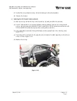
The generator set may be shipped without aircraft cables. The output cables connect to the load
contactors, which are located at the rear of the unit. (See Figure 1-2-3)
The conductor size recommended for AC output cables is 2/0 AWG. Use No. 12 AWG for the E and F
terminals. The lugs must have at least a 3/8-inch diameter hole to fit into the output contactor. (See
Figure 1-2-4) The E and F wires should be fitted with 16 gauge forks or into a double ferrule and then
inserted into the normally open auxiliary contact block attached to the side of the output contactor.
(See Figure 1-2-5)
To install AC output cables proceed as follows:
(1) Remove the canopy. (While this may not be necessary, it greatly simplifies the process.)
(2) Loosen the screws on the cable clamps.
(3) Route the cables through the hole in the cable tray and then through the cable clamps, and up to
the load side of the load contactor(s).
(4) Connect the phase cable terminal lugs to the appropriate terminal studs on the contactor(s): cable
lug A to terminal stud A, B to B, and C to C.
(5)
Connect the cable’s neutral terminal lug securely to the neutral (ground) stud on the power
module assembly. (See Figure 1-2-4)
(6) Connect the E and F cables into the auxiliary contact block on the side of the output contactor..

