OM-2245 / Operation and Maintenance Manual
ITW GSE 4400 / 400 Hz. Generator Set
March 15, 2015
Chapter 1-1
Page 19
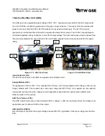
ARU Board (A20):
The ARU Board interfaces with the processor board and the rest of the 28 VDC unit. It has the following
functions:
x
Supplied from G20 (X2)
x
Connection to ARU control input on A2 (X1)
x
Control of thyristors.
x
Measures the output voltage.
x
Interface for heat sink thermostat (X5)
x
Input for current transformer T20 (X6)
Resistor (R20):
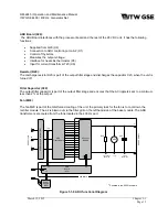
The discharge resistor R20 is part of the output filter stage and discharges the capacitor C20, when the unit is
turned off.
Filter Capacitor (C20)
The output filter capacitor is part of the output filter stage and ensures that the AC ripple is kept to a minimum,
less than 2% at the output.
Fan (M20)
The fan M20 is part of the total forced cooling of the unit, the primary task for the fan is to cool down the
rectifier module. The air is blown out via the filter grill on the left hand side of the base module. The ARU
transformers are cooled from the fans located in the 400 Hz part.
Figure 1-1-9 ARU functional Diagram
*
*
ARU
Board
(A20)
A
B
C
+
-
400
Hz Output Contactor (Q3)
ARU
Transformers
X6
C20
R20
400
H
z Input
28
VDC Output
Rectifier
Module
M20
Power
Supply
(G20)
G20
X2
X1
X6
X5
°t
DISCHARGE
RESISTOR
FAN
FILTER
CAPACITOR
T20
ARU Module
*
Situated in the 400 Hz cubicle

