13
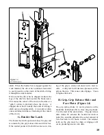
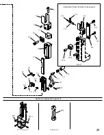
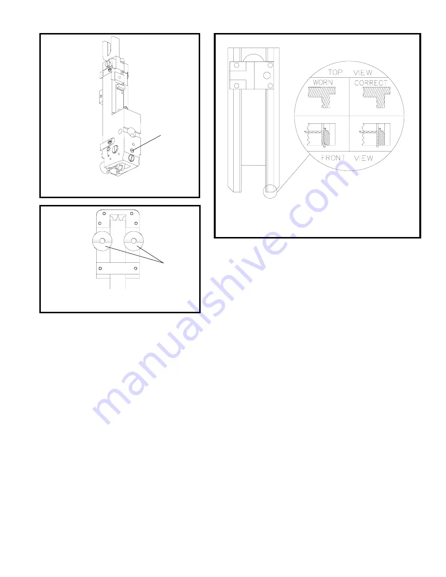
D. Bender Bar (Figure 11)
The bender bar bends the wire over the rotator and
forms it into an unclinched stitch. The legs of the
stitch are guided towards the work material by the
bender bar grooves. The legs of the unclinched
stitch should be perpendicular to the crown. When
the bender bar grooves become worn, the legs tend
to flare out (Figure 11) as they emerge from the
grooves. This causes the legs to strike the clincher
improperly. As a result, one or both legs will
crumple and a broken driver bar or a broken bender
bar can result. If the lower end of the bender bar
grooves become chipped, it will not support the wire
and may cause the stitch to break at the crown. Re-
place the bender bar assembly (See "G" page 15 or
Fig. 12). Other bender bar functions are related to
wire cutting ("I" page 16), and driving ("F" page
14).
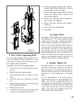
2. To adjust for side-to-side alignment: (Fig. 10)
a. Turn power off. Cycle the stitcher by hand
until legs of the stitch appear just below the
bender bar to determine how far the head or
clincher should be moved to the side.
b. Loosen clincher plate binder nuts (Index A).
c. Move clincher to left or right as required.
d. Tighten binder nuts.
C. Head/Clincher Alignment
(Figure 9, 10)
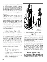
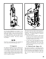
To test alignment: Drive several stitches into a sec-
tion of material identical to that which is to be
stitched. The clinched legs should be identical and
aligned with each other. If the legs are not in align-
ment make one of the following adjustments:
1. To adjust for front-to-rear alignment: (Fig. 9)
a. Turn power off. Cycle the stitcher by hand
until legs of the stitch appear just below the
bender bar to determine if the head should
be moved to the front or rear.
b. Remove stitcher from machine.
c. Turn the head aligning screw (Index D)
clockwise to move the head backward; coun-
terclockwise to move the head forward.
d. Install stitcher head on machine.
D
A
(SK852I)
Figure 11
(CTTT2605 Scene 11)
Figure 9
(CTTT2605 Scene 12)
Figure 10
Inject lube into cutter operating slide.


