background image

2

PRODUCT SPECIFICATIONS

Unit  Weight:

Lbs.
4.5 lbs.

Unit Envelope Size:

Height

Length

Width

M2000 Head Without Wire Guide:

11 in.

3.12 in.

1.82 in.

Notes

Summary of Contents for M2000

Page 1: ...OWNERS MANUAL M2000 ISP Stitching Bindery Products A D i v i s i o n O f S a m u e l S t r a p p i n g S y s t e m s ISP Stitching Bindery Products ...

Page 2: ... Wire 17 Rotator 18 Wire Straighteners 19 Supporter 19 Tension Pawl 20 Dismantling M2000 Head Section 6 PARTS LIST 22 M2000 Head Stitcher Section 1 INTRODUCTION 1 Model and Serial Number 2 Product Specifications Section 2 SAFETY PRECAUTIONS AND PROCEDURES 3 Safety 3 Safety Guards Cover Section 3 ASSEMBLIES LUBRICATION INSTALLATION 4 Before Unpacking 4 After Unpacking 4 Assembly 4 Threading wire an...

Page 3: ...formance from your stitcher and is divided into 6 major sections Read the M2000 Manual thoroughly Study it carefully Best stitching performance will be assured if all the adjustments are made as instructed When ordering parts or requesting information please state Quantity required part number part name model wire size crown width stitcher head part number and stitcher head serial number Stitcher ...

Page 4: ...2 PRODUCT SPECIFICATIONS Unit Weight Lbs 4 5 lbs Unit Envelope Size Height Length Width M2000 Head Without Wire Guide 11 in 3 12 in 1 82 in Notes ...

Page 5: ...r cut 4 Wear adequate safety equipment for eye and face protection Observe your plant safety rules 5 Practice good housekeeping in your work area Keep it as clean and uncluttered as possible 6 A well maintained machine is a safer machine Clean and lubricate the machine at regular intervals Check machine daily for broken or worn parts Replace as necessary DO NOT attempt to operate the machine if a ...

Page 6: ...re Index A by hand from the coil 2 Thread the wire through the slot Index B at the end of the wire guide spring through the wire guides Index C between the thin and thick felt wire wipes Index D through the upper wire straightener Index E and through the lower wire straightener Index F A From wire coil C H G J K F B C E 3 Release the rotator operating spring Index H from the rotator and swing it t...

Page 7: ...er at anytime without work under the head FELT WIPE PADS LUBRICATION AND MAINTAINANCE FIGURE 2 IMPORTANT In order for the stitchers to operate properly the felt wire wipes MUST be rotated and dampened with SAE 20W oil before each new spool of wire 50 000 to 70 000 stitches Replace felt pads when they become so dirty that they cannot be rotated to a clean spot Figure 2 Dirty area of pads has been s...

Page 8: ...ATION FIGURES 3 4 Figure 3 H B C A D E F G CTTT2605 Scene 6 E Wipe clean inside of rotator holder F Inject a small amount of lube into cam area of driver bar G Inject lube into cutter operating slide H Wipe driver clean and apply a light coating of lube After prolonged use or storage accumulations of wire dust dirt or other contaminants can mix with the stitcher lubricant This will reduce the lubr...

Page 9: ...wire feeding unless you have work material between the clinchers and formers 2 Do not drive one stitch on top of an other Changing Work Thickness Figure 5 Changing work thickness will probably require a change of the wire draw length used to make a stitch This is done by raising or lowering the face plate Change face plate position as follows 1 Switch off power loosen the face plate screw Index A ...

Page 10: ...NAME QTY Wire Cutters 2 Grip 1 Grip Spring 1 Tension Roll Clip 2 Rotator 1 Clincher Points 2 Caution MAKE ALL ADJUSTMENTS WITH THE POWER OFF AND THE STITCHING HEAD IN NEUTRAL POSITION Fig 6 In neutral position the wire grip assem bly Index A is stopped at the top of the slot in the face plate Stitching Adjustments Best stitching performance will be assured if all adjustments are made so that you g...

Page 11: ...of Stitch Page 8 H Page 15 H Page 15 Replace M Page 18 F Page 14 O Page 19 H Page 15 1 One or both legs buckled NOTE Since buckled legs are often concealed in the work and may appear the same as a short leg always remove two or more stitches to see which is occur ring 1 Clincher is worn or improperly aligned 2 Insufficient compression 3 Unequal leg length 1 Leg Lengths not adjusted properly 2 Grip...

Page 12: ...l cutters 7 Flat piece of wire L Page 17 M Page 18 L Page 17 L page 17 8 Stitches come out in pieces L Page 17 L Page 17 M Page 18 K Page 17 D Page 13 9 Both stitcher legs are either too long or too short See Changing Work Thickness Page 7 C Page 13 I Page 16 1 Rotator is dirty 2 Improperly adjusted lower wire straightener 3 Broken or worn rotator 4 Improperly aligned rotator Face plate not adjust...

Page 13: ... 14 2 Wire Buckles above the wire cutters and below the grip 1 Improperly aligned rotator 2 Worn or broken wire cutters 3 Burrs on rotator 4 Improperly adjusted lower wire straightener 5 Worn or broken wire cutter operating slide 6 Wire cutter slot in face plate worn L Page 17 I Page 16 L Page 17 M Page 18 J Page 17 I Page 16 C GRIP 1 Grip does not close 1 Face plate is too high See Changing Work ...

Page 14: ... the stitch legs to buckle and or the cor ners of the crown to fracture With the Activated moving Type clincher the stitch legs must enter the clincher at the same time and with equal spacing from each side When the CAUTION Turn Power OFF Before making Any Adjustments stitch legs have penetrated the work material the moving clinchers are raised to bend the legs to wards each other and up flat agai...

Page 15: ...er off Cycle the stitcher by hand until legs of the stitch appear just below the bender bar to determine how far the head or clincher should be moved to the side b Loosen clincher plate binder nuts Index A c Move clincher to left or right as required d Tighten binder nuts C Head Clincher Alignment Figure 9 10 To test alignment Drive several stitches into a sec tion of material identical to that wh...

Page 16: ... bar assembly to continue downward with the end of the driver riding on top of the formed E Bender Bar Friction Plug And Or Spring Fig 12 Two parts furnish pressure to coordinate movement of driver bar and bender bar If pressure is insuffi cient proper timing is not maintained for the action of the grip As a result wire feeds backwards Replace the plug and or spring To replace bender bar friction ...

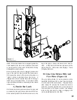
Page 17: ...er bar latch opens and closes the grip and is actuated by the grip release slide and driver bar If the contact points of the latch become worn tim F ing of the grip is erratic and uneven wire feed re sults A dirty latch will decrease preassure of the grip on the wire This causes wire slippage Clean or replace the latch H Grip Grip Release Slide and Face Plate Figure 14 The grip spring Index A exer...

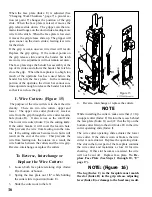
Page 18: ... cutter Index C is the cutting knife If the cutter breaks it will cover the lead in hole This prevents the wire from feeding into the rota tor If the cutting surfaces become worn burrs will result on the end of the wire This prevents the wire from feeding into the rotator As a result the wire buckles between the cutters and the wire grip Reverse interchange or replace the cutters To Reverse Interc...

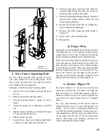
Page 19: ...the wire from the cutoff die 2 holds the wire while it is being cut then 3 turns it to a horizontal position moves it under the bender bar grooves and 4 supports the wire while it is being formed into a U shaped stitch The wire lead in funnel of the rotator must be aligned with the wire as it comes through the wire cutters If the rotator is improperly aligned the wire hits the rotator and buckles ...

Page 20: ...able or against other hand With proper magnetic holding force wire will remain in rotator With insufficient holding force wire will fall from rota tor Replace the rotator The rotator holder and rotator operating spring are responsible for alignment of the wire beneath the bender bar grooves The position of the rotator holder determines how far the rotator is pushed forward under the bender bar by ...

Page 21: ...insure the accurate feeding of wire If the corners of the top surface of the supporter are too sharp or nicked the corners of the stitch crown will fracture If operating properly the supporter should function as follows 1 When the bender bar touches the work material and the legs of the stitch are about to leave the bender bar grooves the supporter should be touching the underside of the crown 2 A...

Page 22: ... can be installed backwards Be sure to read and follow the instructions F on page 21 before reassembling 6 Remove the two lower clips 5 Remove the upper face plate clips 7 Position grip spring housing between tension pawl spring retainer and cutter housing 8 Remove face plate by sliding face plate to the left and lifting up 10 Remove friction plug and spring 12 Remove rotator holder 11 Remove grip...

Page 23: ...ex A is visible and is aligned with slot Index B of rotator operating cam Index C If not assembled in this way the bonnet casting will crack or break on the next cycle under power It is recommended that the stitcher be cycled by hand to test that proper r e a s s e m b l y procedure has been followed DISMANTLING REASSEMBLING M2000 HEAD DO NOT REMOVE OR ADJUST THESE TWO SCREWS CTT2605 Scene 5 F D T...

Page 24: ...n Heads Figures 20 Section 6 PARTS LIST Figure 19 CTTT2605 Scene 24 CB75B Iso View 28 31 32 24 34 44 40 35 36 38 32 37 33 39 42 40 29 32 43 46 45 56 47 31 58 59 61 49 30 32 31 41 48 49 50 51 52 53 54 55 57 B5 B6 B7 B8 B3 B2 B1 CTTT2605 Scene 25 SK885 Scene 2 SK885 Scene 1 B4 60 ...

Page 25: ...Adjustable Stroke Position Components 6A 25A 4A 2A 1A 7A 5A 8A 26A SK852R 2 27 25 26 10 14 20 18 19 16 17 3 1 9 23 22 21 11 12 15 13 B11 B9 B10 CTT2604L Layout 2 CA44 Layout 2 Special Components Figures 21 ...

Page 26: ...RE GUIDE SPRING BRKT ADJ SCREW 1 3 CA9077 WIRE GUIDE SPRING BRKT SET SCREW 1 4A CT1060 SET SCREW 1 5A CT2616 WIRE GUIDE BRACKET ADJ SCREW STUD 1 6A CT2614 FACE PLATE ADJ SLIDE GUIDE STUD 1 7A CT2612 FACE PLATE LOCATING BLOCK STUD 1 8A CT2610 FACE PLATE ADJUSTING SLIDE 1 9 See TABLE 1 DRIVING SLIDE ASSEMBLY 1 NOTE The Driving Slide Assembly includes the following parts DRIVINGSLIDE ONLY 1 a c d f C...

Page 27: ...L 2 52 CA9098 TENSION PAWL 1 53 CA9065A STRAIGHTENER ECCENTRIC ROLL 1 54 CA9066A WIRE STRAIGHTENER ECCENTRIC 1 55 CA172 ECCENTRIC FRICTION LOCKING SCREW 1 56 ROTATOR HOLDER 1 CA9043M 1 2 CR 25 TO 30 RD WIRE TAPERED END CA9043L 1 2 CR 25 TO 30 RD WIRE CA9043N 1 2 CR 20 21X25 WIRE CA9043P 1 2 CR 25 TO 30 RD WIRE R H Not Shown 57 CB75B KEY WOODRUFF 1 for use with CA 9043 M Rotator Holder only 58 CAA9...

Page 28: ... Includes CA 9083 A CTT 9086 M CT 9093 A CA 2091 CT 9088 Includes CA 9083 A CTT 9086 V CT 9093 A 1 16 Nominal CA 9083 A Thick 1 2 Crown 1 32 Nominal CA 9083 Thin 1 2 Crown CLINCHER POINT D E F G H J L L L L CLINCHER SLIDES L SK852M2 SK852N2 SK85202 SK852P2 SK852Q2 SK852R2 TYPE A1 A2 A3 A1 A2 A3 CTT9086A Layout 2 CTT9086M Layout 2 CTT9086V Layout 2 CA 2090 CT 9088 CA 2091 Stud Binderbolt Nut SK852J...

Page 29: ...h CTT2133D2 1 3 4 5 6 7 8 9 11 12 2 ITEM PART NO DESCRIPTION QTY ITEM PART NO DESCRIPTION QTY 10 2 CB651E SCREW 10 32x2 000 1 3 CA9651 WASHER 2 4 CA9652 FELT WASHER THICK 1 5 CA9653 FELT WASHER THIN 1 6 CA9032C SPRING COMPRESSION 1 7 CB860B NUT 10 32 ELASTIC STOP 1 8 CA9065A ROLLER ECCENTRIC 1 9 CA172 SCREW NYLON TIP 1 10 CA9103C ROLLER WIRE STRAIGHTENER 2 11 CA9124 CLIP ROLLER 2 12 CA9066A ECCENT...

Reviews: