background image

Page 

9


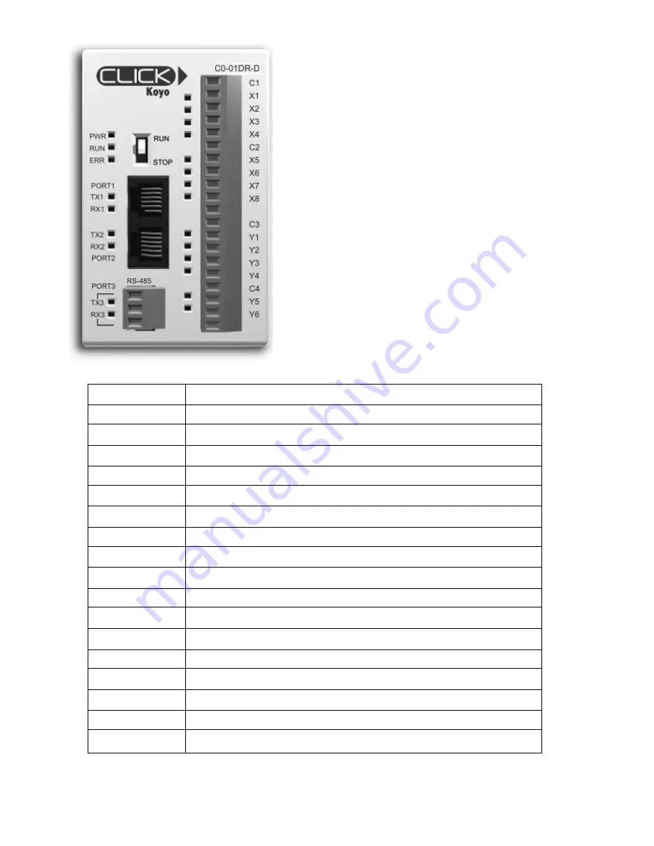
PLC Overview: 


Each RLA Style 3 Controller is equipped with a 
Micro-PLC to control all of its functions. 
 
The PLC comes programmed and wired from the 
factory and should not be altered in any way. 
 

Note:

 All units will be shipped with the PLC 

Mode switch in the STOP position. It should 
remain in this position until Start-Up testing is 
going to be performed. Once ready to test the 
system, the switch must be set to the RUN 
position for the controller to function. 

Indicator Light 

Description of Status When Light is On 

PWR 

PLC has 24VDC from Power Supply 

RUN 

PLC is set to RUN Mode and is operational 

ERR 

PLC Processor has incurred an error 

X1 

Door Panic Button is being pressed 

X2 

Alarm signal being received (Dry-Contact) 

X3 

Leak Sensor signal being received (Dry-Contact) 

X4 

Leak Sensor signal being received (Dry-Contact) 

X5 

Freeze Sensor signal being received (Dry-Contact) 

X6 

Seismic Sensor signal being received (Dry-Contact) 

X7 

Not Used 

X8 

Not Used 

Y1 

Circuit 1 active (Water - Supply) 

Y2 

Circuit 2 active (Water - Drain Down) 

Y3 

Circuit 3 active (Gas Supply) 

Y4 

Circuit 4 active (Electrical Shunt) 

Y5 

Beacon Output (ON with service) 

Y6 

Beacon Output (OFF with service) 

Table 1 

Summary of Contents for RLA Series

Page 1: ...3 Residential Water Leak Detection RLA 3 Installation Maintenance Operations and Start up Instructions Read all instructions BEFORE installation and USE of Controller KEEP INSTRUCTIONS FOR FUTURE USE...

Page 2: ...d monitoring systems The system should be thoroughly tested and adjustments made at time of initial operation Periodic testing should be conducted by the user to assure that all components function an...

Page 3: ...nnecting Controlled Services 10 Battery Backup 10 Connecting Alarm Monitoring Wiring 11 Start Up Checklist 11 Start Up Test Preliminary Information 11 Start Up Test 12 Equipment Operation 13 Troublesh...

Page 4: ...be confirmed prior to installation Enclosed with this Manual is a separate registration form The front of the form is for equipment warranty registration The back is a copy of the equipment start up c...

Page 5: ...Page 5...

Page 6: ...n time to ensure that this occurs A Flush Mounting Trim Flange is provided with each flush mounted unit Separate installation instructions and hardware are included with this flange Semi and Flush Tri...

Page 7: ...e followed when connecting the conduit to the service panel Figure 4 Controller Knock out holes Wiring the RLA Controller Important Verify that the electrical supply is disconnected prior to connectin...

Page 8: ...extend lock position STEP 4 Installing Flush Door Trim Figure 7 Prior to installing Door Trim ensure that wall finishes are complete and that the door panel has been installed To install the Flush Doo...

Page 9: ...escription of Status When Light is On PWR PLC has 24VDC from Power Supply RUN PLC is set to RUN Mode and is operational ERR PLC Processor has incurred an error X1 Door Panic Button is being pressed X2...

Page 10: ...ctly to the Output Terminal in order to function as intended Connect Supply Solenoid to the ON w Latch Terminals Make connections to BLK and WHT pins to match instructions provided with the solenoids...

Page 11: ...ct short or input voltage at the output circuit will cause damage to the PLC and Controller Verify that the Door Panel plug is firmly secured to its terminal and ground wire is connected Examine Door...

Page 12: ...ing system a Press and release the red Panic Button b Verify that all Solenoids have been deactivated 2 Press the Reset System button on the screen NOTE Electrical Service will not shut down with Pani...

Page 13: ...l breakage in piping or circuits may cause damage to the facility Integral time delay programming insures that brief seismic or similar activity will not affect services To Activate One or More of the...

Page 14: ...l In many cases failure of the system is the result of improper connection of a remote service or device such as a remote relay solenoid or building alarm system Refer to Equipment Specifications to c...

Page 15: ...all moisture is removed from the compartment The electronic controller PLC is sensitive to moisture dust debris and other air borne particles Do not expose the interior compartment of the enclosure Du...

Page 16: ...not specifically intended for use in applications where a master shut down and re instate device is located away from areas of normal use ISIMET s opinion is that in such cases there is risk that the...

Reviews: