background image

9

Quick Setup

Step 4:  Finish Installation

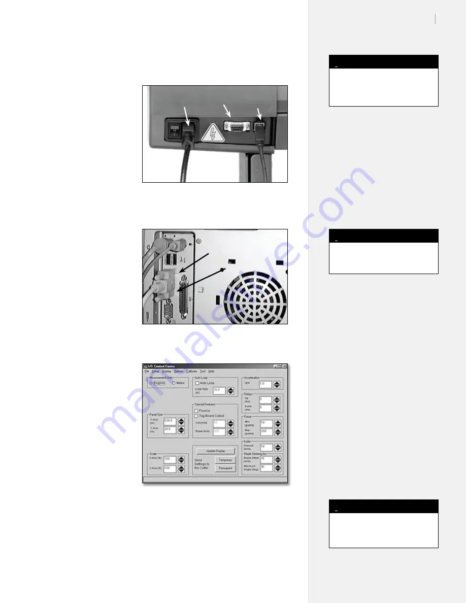
Connect the 
Machine Cables

Make sure power is 

off  to the cutter (the 

switch is placed in the 

0

 position). Connect 

the serial or USB cable 

and the power cord 

to the panel on the 

back of the right side 

of the cutter. Plug the 

machine power cable 

into a wall socket or 

surge protector.

Connect the 
Computer Cable

With power to the 

computer off, connect 

the serial or USB cable 

to one of the ports 

on the back of the 

computer. 

See the In-

stallation chapter of the 

SmarTrac User Guide


for more information. 

Install the 
Software

Insert the installation 

CD-ROM into the 

computer CD-ROM 

drive. The install 

program should start 

automatically. If it 

does not, select 

Run


from the 

Start Menu

Browse to the CD-

ROM and double-click 

on 

Install Ioline Con-

trol Center

 from the 

list of options. Press 

OK

 to start the install. 

Install the 

Control 

Center

 software.

Install USB Drivers

Please see the guide labeled 

Installing USB Drivers for Ioline Products


on the CD-ROM for the driver installation process.

Figure 12. 

Power cable and communication ports.

Figure 13. 

Computer communication ports.

Power 
Cable

Serial 
Port

USB 
Port

USB Ports

Serial Port

Figure 14. 

The Ioline 

Control Center

.

A USB cable is provided in the 

Accessory Kit.

Note

i

The Setup program also allows 

installation of the electronic User 

Guides and the necessary viewer.

Note

i

An adapter (not included) is re-

quired for 25-pin serial connections.

Note

i

Summary of Contents for I/S 100 System

Page 1: ...1 Quick Start Guide Ioline SmarTrac I S Series SC Series I S 60 85 110 130 and 100 System SC 40 48 ...

Page 2: ... maintain it in proper working condition by following the instructions in this User Guide It is the responsibility of the operator of the cutter to follow all safety precautions and warnings that are described in this User Guide Ioline is not responsible for inju ries that may occur as a result of unsafe operating procedures Ioline is not responsible for substandard operational performance as a re...

Page 3: ...cal adjustments are necessary turn off the cutter and disconnect it from all power sources both the computer and the wall outlet n Be careful with hair jewelry or loose clothing near the cutter They can become caught in the mechanical parts n Never move the carriage by hand Use the Arrow keys and let the machine do it n Keep hands away from the carriage when the cutter is in opera tion The carriag...

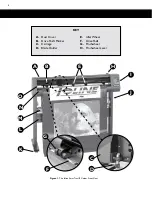
Page 4: ...A Dust Cover B Drive Shaft Marker C Carriage D Blade Holder E Idler Wheel F Drive Shaft G Pinchwheel H Pinchwheel Lever KEY Figure 1 The Ioline SmarTrac I S Cutter FrontView A B H J E I L M N O K D C G F ...

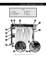
Page 5: ...ference Guide Figure 2 The Ioline SmarTrac Contour SC Cutter FrontView I Keypad J Stand Leg K Stand Leveling Foot L Cross member M Media Roller N Platen O Traverse P LED Sensor KEY A B E H J K L M N O D P C G F I ...

Page 6: ...n 7 16 in wrench Step 2 Assemble the Stand Optional for I S 60 model Attach the Feet Attach one foot to each leg using three 1 5 in long Phillips screws and three 7 16 in hex nuts Repeat this procedure for the other leg Screw all of the leg level ers halfway into the ends of the stand feet Thread all four levelers in equally to ensure your cutter is level and stable Figure 5 Attach the feet Levele...

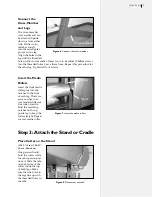
Page 7: ...ins into the notches in the front of each leg There are extra notches to ac commodate different size rolls of media Find the matching notches on the op posite leg to keep the roller straight Repeat for rear media roller Figure 6 Connect the cross member Figure 7 Insert the media rollers Cross member Roller Notch Tab Step 3 Attach the Stand or Cradle Place Cutter on the Stand I S 85 110 and 130 SC ...

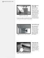
Page 8: ...cradle leg Figure 9 Place cutter on cradle Tab Front Back Finish Assembly Cut the plastic strap that holds the car riage in place during shipment and discard it Remove and dis card all packing foam from around the car riage to complete the assembly Insert the Screws Have one person hold the cutter while the other person inserts the screws to secure the cutter to the legs or cradle feet Insert the ...

Page 9: ...M drive The install program should start automatically If it does not select Run from the Start Menu Browse to the CD ROM and double click on Install Ioline Con trol Center from the list of options Press OK to start the install Install the Control Center software Install USB Drivers Please see the guide labeled Installing USB Drivers for Ioline Products on the CD ROM for the driver installation pr...

Page 10: ...heel positions for a variety of material widths Evenly space the inner idler wheel s I S 85 110 and 130 SC 40 and 48 mod els over drive shaft segments Make sure there is a minimum of one inch between the edge of the roll and the stand leg Square the Material Lift the pinchwheels off the drive shaft using the pinchwheel lever Pull enough material through the machine so that it reaches the roll Alig...

Page 11: ...e blade tip is barely inside the foot with no blade exposed Loosen the thumb screw on the carriage jaw and insert the blade holder The flange slides into the slot in the jaw Rotate the clamp down onto the flange and tighten the thumb screw until the blade holder is held securely in place Adjust the Blade Exposure and Force Turn the Force knob on the keypad clock wise to maximum Press the Test Cut ...

Page 12: ...s a final check Move the carriage and material to a starting position for the first file Press the Set Ori gin key on the keypad The light on the keypad will turn green The cutter is ready to cut Refer to the User Guide and your design software documentation for more information about optimizing cutter performance Customer Service Ioline Corporation is committed to providing quality service and su...

Reviews: