MH860 series hydraulic servo drive
Electrical connection
33
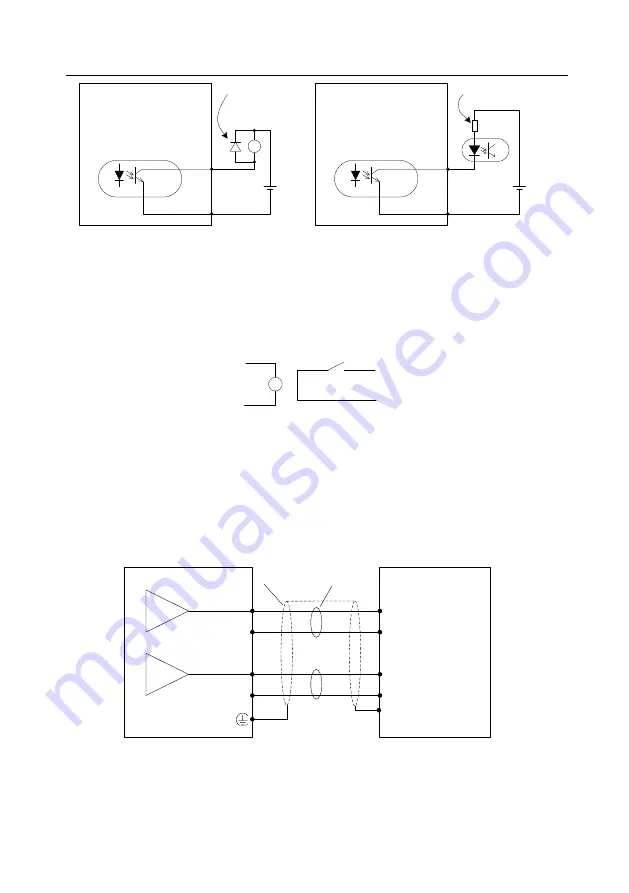
Connect a free-wheeling
diode if an inductive load is
connected.
Max. load capacity of each
output terminal: 30V, 50mA
DC
12~24V
+
-
Drive side
O+
O1
Max. load capacity of each
output terminal: 30V, 50mA
+
-
RY
DC
12~24V
①
Connecting to a relay coil
②
Connecting to an optical coupler
O+
O-
Connect to a current limit
resistor if an optical coupler
is connected.
Drive side
Max. voltage: DC30V
Max. current: DC50mA
2.
The relay output circuit is described as follows:
For pins 1 to 2 of CN1A connector:
Digital output signal (O1) is output from the relay. The following shows the interface circuit
O+
O-
Contact capacity: 3A/250VAC, 1A/30VDC
3.
The analog output circuit is described as follows:
For pins 5 to 6 of CN5 connector:
Analog output signals (AOUT1, AOUT2) are output from the OPA, with which the AGND
makes up an output circuit. You can select internal parameter output through the LED panel,
HMI, or SCM. By default, AOUT1 is pressure output, while AOUT2 is motor speed output. The
following shows the interface circuit.
Measuring instrument or
external circuit
Shielded
cable
Connect the shielded
cable according to
equipment requirement
Servo drive
Twisted
pair
GND
GND
AIN1
AIN2
AOUT1 5
AOUT2 6
GND 4
GND 4
Output accuracy: 10-bit D/A
Voltage range: 0
–10V
Max. current: DC10mA


