Goodrive800 Pro Series Inverter Unit Hardware Manual
Electrical installation
202202 (V1.0)
45
4.4.2
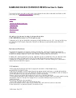
Isolation switch connection
4.4.2.1
Electrical connection
D
C
-
D
C
+
A2
A1
1
3
2
4
14
13
DC-
DC+
A2
A1
48V
0V
L
N
External AC 220V power
Inverter
unit
QS
PG
R
KM
Note:
QS indicates the isolation switch, KM indicates the DC contactor, while R indicates the buffer resistor;
QS and KM form the main circuit, while QS and R form the buffer circuit connected in parallel to the
main circuit.
13–14 indicate QS feedback signals.
X1 indicates the indicator.
4.4.2.2
Procedure
Step 1
Initial state
QS is opened, KM is not closed, 13 and 14 are in N.O. state, while X1 has no indication.
Step 2
Precharge state
QS is closed, KM is not closed, the buffer circuit is started through the loop between QS and R to precharge
the inverter unit, 13 and 14 are in N.C. state, while X1 has no indication.
Step 3
Working state
QS is closed, the inverter unit finishes charging, the bus voltage has been established with output of DC 48V
voltage, KM is closed, while the main circuit is switched on.
Note: The QS electrical interlock coil must be powered by external power supply of AC 220V, so that QS
cannot be operated with electricity.