background image

10

Combustion and Ventilation  

Air Requirements

T

O


AVOID


PROPERTY


DAMAGE

PERSONAL


INJURY


OR


DEATH

SUFFICIENT


FRESH


AIR


FOR


PROPER


COMBUSTION


AND


VENTILATION


OF


FLUE


GASES


MUST


BE


SUPPLIED

. M

OST


HOMES


REQUIRE


OUTSIDE


AIR


BE


SUPPLIED


INTO


THE


FURNACE


AREA

.

WARNING

Improved construction and additional insulation in buildings 

have reduced heat loss by reducing air infiltration and escape 

around doors and windows.  These changes have helped in 

reducing heating/cooling costs but have created a problem 

supplying  combustion  and  ventilation  air  for  gas  fired  and 

other fuel burning appliances.  Appliances that pull air out 

of the house (clothes dryers, exhaust fans, fireplaces, etc.) 

increase the problem by starving appliances for air.  
House depressurization can cause back drafting or improper 

combustion of gas-fired appliances, thereby exposing building 

occupants to gas combustion products that could include 

carbon monoxide.
If this furnace is to be installed in the same space with other 

gas appliances, such as a water heater, ensure there is an 

adequate supply of combustion and ventilation air for all 

appliances.  Refer to the latest edition of the National Fuel 

Gas Code NFPA 54/ANSI Z223.1 or applicable provisions of 

the local building codes for determining the combustion air 

requirements for the appliances.

This furnace must use indoor air for combustion. It cannot be 

installed as a direct vent (i.e., sealed com bustion) furnace. 

Most homes will require outside air be supplied to the furnace 

area by means of ventilation grilles or ducts connecting directly 

to the outdoors or spaces open to the outdoors such as attics 

or crawl spaces. A furnace installed in a confined space (i.e., 

a closet or utility room) must have two ventilation openings 

with a total minimum free area of 0.25 square inches per 

1,000 BTU/hr of furnace input rating. Refer to Specification 

Sheet applicable to your model for minimum clearances to 

combustible surfaces. One of the ventilation openings must 

be within 12” of the top; the other opening must be within 12” 

of the bottom of the confined space. In a typical construction, 

the clearance between the door and door frame is usually 

adequate to satisfy this ventilation requirement.

Category I Venting (Vertical Venting)

T

O


PREVENT


POSSIBLE


PERSONAL


INJURY


OR


DEATH


DUE


TO


ASPHYXIATION

THIS


FURNACE


MUST


BE

 C

ATEGORY

 I 

VENTED

. D

O


NOT


VENT


USING

 C

ATEGORY

 III 

VENTING

.

WARNING

Category I Venting is venting at a non-positive pressure.  A 

furnace vented as Category I is considered a fan-assisted 

appliance and the vent system does not have to be “gas tight.”  

NOTE:

  Single stage gas furnaces with induced draft blowers 

draw products of combustion through a heat exchanger 

allowing, in some instances, common venting with natural 

draft appliances (i.e. water heaters). All installations must be 

vented in accordance with the latest edition of the National 

Fuel Gas Code NFPA 54/ANSI Z223.1 . 

Note: 

The vertical height of the category 1 venting system 

must be at least as great as the horizontal length of the vertical 

system. 

T

O


PREVENT


POSSIBLE


PERSONAL


INJURY


OR


DEATH


DUE


TO


ASPHYXIATION

COMMON


VENTING


WITH


OTHER


MANUFACTURER

S


INDUCED


DRAFT


APPLIANCES


IS


NOT


ALLOWED

.

WARNING

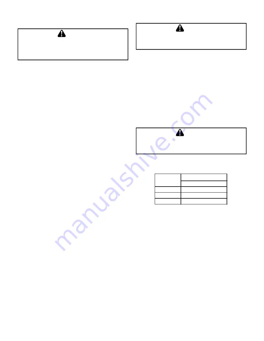
The minimum vent diameter for the Category I venting system 

is as shown:

MINIMUM VENT

UPFLOW

40

4 Inch

60

4 Inch

80

4 Inch

MODEL

Table 2

Under some conditions, larger vents than those shown above 

may be required or allowed.  

When an existing furnace is 

removed from a venting system serving other appliances

, the 

venting system may be too large to properly vent the remaining 

attached appliances.

Summary of Contents for MES80

Page 1: ...ION 6 LOCATION REQUIREMENTS AND CONSIDERATIONS 7 Clearances and Accessibility 8 Installation Positions 8 Venting For Horizontal Left Or Right Installations 8 Horizontal Installation 8 Furnace Suspensi...

Page 2: ...ustment 23 Gas Input Rate Measurement Natural Gas Only 23 Temperature Rise 24 Circulator Blower Fan Timing Adjustment 24 OPERATIONAL CHECKS 25 Checking Duct Static 25 SAFETY CIRCUIT DESCRIPTION 25 Gen...

Page 3: ...ce qui peut entra ner la mort des blessures ou des dommages mat riels IF THE INFORMATION IN THESE INSTRUCTIONS IS NOT FOLLOWED EXACTLY A FIRE OR EXPLOSION MAY RESULT CAUSING PROPERTY DAMAGE PERSONAL I...

Page 4: ...nt pas suivies pour chacun des appareils raccord s au syst me de ventilation au moment de sa mise en marche cela peut entra ner une intoxication au monoxyde de carbone ou la mort Les tapes suivantes d...

Page 5: ...ing precautions during furnace installation and servicing to protect the integrated control module from damage By putting the furnace the control and the person at the same electrostatic potential the...

Page 6: ...furnace A return air temperature range between 60 F 16 C and 80 F 27 C is maintained Air filters are installed in the system and replaced daily during construction and upon completion of construction...

Page 7: ...icals halogen type refrigerants printing inks cleaning solutions such as perchloroethylene paint removers varnishes hydrochloric acid cements and glues antistatic fabric softeners for clothes dryers m...

Page 8: ...gas electrical and drain line connections NOTE In addition to the required clearances to combustible materials a minimum of 24 service clearance must be available in front of the unit Installation Po...

Page 9: ...ndition c In so far as practical close all building doors and windows and all doors between the space in which the appliance s connected to the venting system are located and other spaces of the build...

Page 10: ...oset or utility room must have two ventilation openings with a total minimum free area of 0 25 square inches per 1 000 BTU hr of furnace input rating Refer to Specification Sheet applicable to your mo...

Page 11: ...PPED APPLIANCE THE POTENTIAL FOR CONDENSATION DAMAGE MAY STILL EXIST WITH EXTREMELY COLD CONDITIONS LONG VENT CONNECTORS EXTERIOR CHIMNEYS OR ANY COMBINATION OF THESE CONDITIONS THE RISK OF CONDENSATI...

Page 12: ...existing metal liners are correctly installed and in good condition Remove the lowest existing vent connector and examine the inside of the elbow or tee at the base of the liner A small amount of soo...

Page 13: ...y recognized building codes or standards One such standard which may be referenced is the Standard for Chimneys Fireplaces Vents and Solid Fuel Burning Appliances ANSI NFPA 211 Remember that all appli...

Page 14: ...or thimbles must be used to prevent the B vent from coming into direct contact with the tile liner or chimney walls Direct contact would result in higher heat loss with an increased possibility of poo...

Page 15: ...s or by the rotation of the fan Also confirm that wiring location will not interfere with fil ter removal or other maintenance After the junction box is in the desired location use washers to connect...

Page 16: ...p in a fossil fuel application A fossil fuel application refers to a combined gas furnace and heat pump installation which uses an outdoor temperature sensor to determine the most cost efficient means...

Page 17: ...f old pipe is used be sure it is clean and free of rust scale burrs chips and old pipe joint compound Use pipe joint compound on male threads ONLY Always use pipe joint compound pipe dope that is APPR...

Page 18: ...size that the heat exchanger can be viewed for visual light inspection or such that a sampling probe can be inserted into the airstream The access panel must be made to prevent air leaks when the furn...

Page 19: ...be installed in the central return register or a side panel external filter rack kit upflows As an alternative a media air filter or electronic air cleaner can be used as the primary filter The follo...

Page 20: ...have 5 media filters and are available in the following configurations Consult your distributor for information on our complete line of IAQ Clean Comfort products Air cleaner installation location Ma...

Page 21: ...call for fan Circulator blower is de energized Electronic air cleaner terminals are de energized Furnace awaits the next call from thermostat Start up Procedure And Adjustment Furnace must have a 120...

Page 22: ...stem 3 Inlet pressure tap connections a White Rodgers valve Back inlet pressure test screw inlet pressure tap out one turn counterclockwise not more than one turn 4 Connect calibrated U tube manometer...

Page 23: ...regulator cover screw 10 Turn OFF all electrical power and gas supply to the system 11 Remove the manometer hose from the hose barb fitting or outlet pressure Tap 12 Replace outlet pressure tap a Whit...

Page 24: ...onvert capacity to tons Example Cooling Capacity of 30 000 BTU hr 30 000 12 000 2 5 Tons 2 Determine the proper air flow for the cooling system Most cooling systems are designed to work with air volum...

Page 25: ...Operational Checks TO AVOID PERSONAL INJURY OR DEATH DO NOT REMOVE ANY INTERNAL COMPARTMENT COVERS OR ATTEMPT ANY ADJUSTMENT ELECTRICAL COMPONENTS ARE CONTAINED IN BOTH COMPARTMENTS CONTACT A QUALIFIE...

Page 26: ...ure activated sensor It guards against overheating resulting from insufficient air passing over the heat exchanger The auxiliary limit control is suitable for both horizontal right and horizontal left...

Page 27: ...Y OR DEATH DISCONNECT ELECTRICAL POWER BEFORE REMOVING FILTERS NEVER OPERATE FURNACE WITHOUT A FILTER INSTALLED BECAUSE DUST AND LINT WILL BUILD UP ON INTERNAL PARTS RESULTING IN LOSS OF EFFICIENCY EQ...

Page 28: ...lthough only functional parts are shown in the parts list all sheet metal parts doors etc may be ordered by description Parts are available from your distributor Functional Parts List Gas Valve Natura...

Page 29: ...10 Integrated Control Module 11 Transformer 12 Blower Door Interlock Switch 13 Circulator Blower Component ID Tubular Heat Exchanger Pressure Sensor Assembly Flue Pipe Connection Gas Line Entrance Ga...

Page 30: ...in Electrostatic Discharge section of manual Furnace Fails to operate Control LED is flashing TWO 2 RED flashes 2 Flashes RED Pressure sensor indicates pressure reading when it should be zero Faulty...

Page 31: ...ockage or excessive wear and replace as needed Check and correct pressure sensor wiring Turn power OFF prior to repair Replace induced draft blower with proper replacement part LED is steady on Steady...

Page 32: ...combustion noise during heating Insufficient combustion air or high input Blocked flue and or air inlet pipe or faulty induced draft blower or pressure sensor Check and correct gas supply and manifol...

Page 33: ...7 26 1663 27 1620 1588 1546 Orange 898 49 794 NA 723 NA 656 NA 588 NA 522 449 384 Black 1443 31 1388 32 1339 33 1292 34 1242 36 1202 1155 1107 Brown 1601 28 1559 29 1513 29 1473 30 1413 31 1405 1365 1...

Page 34: ...D JUNCTION INTEGRATED CONTROL INTERNAL TO 0140F02416 A 2 MANUFACTUR S SPECIFIED REPLACEMENT PARTS MUST BE USED WHEN SERVICING 1 SET HEAT ANTICIPATOR ON ROOM THERMOSTAT AT 0 7 AMPS NOTES HI VOLTAGE FIE...

Page 35: ...35 THIS PAGE INTENTIONALLY LEFT BLANK...

Page 36: ...ering your product is a relatively short process and entitles you to additional warranty protection except that failure by California and Quebec residents to register their product does not diminish t...

Reviews: