background image

21

User Manual

increases. This is for the purpose of filtering out surface clutter.

3.1.9.4

STC Length

If STC is Custom, it is possible to change the Length of the Sensitivity Time

Constant.

3.1.9.5

STC Strength

If STC is Custom, it is possible to change the Strength of the Sensitivity Time

Constant.

3.1.9.6

Surface Noise Filter

This function implements an advanced time varying filter that allows suppressing

the surface clutter efficiently while leaving fish targets visible.

NOTE

Thus imposing the capability of the Fish Finder to correctly detect the weakest

echoes coming from a very deep bottom.

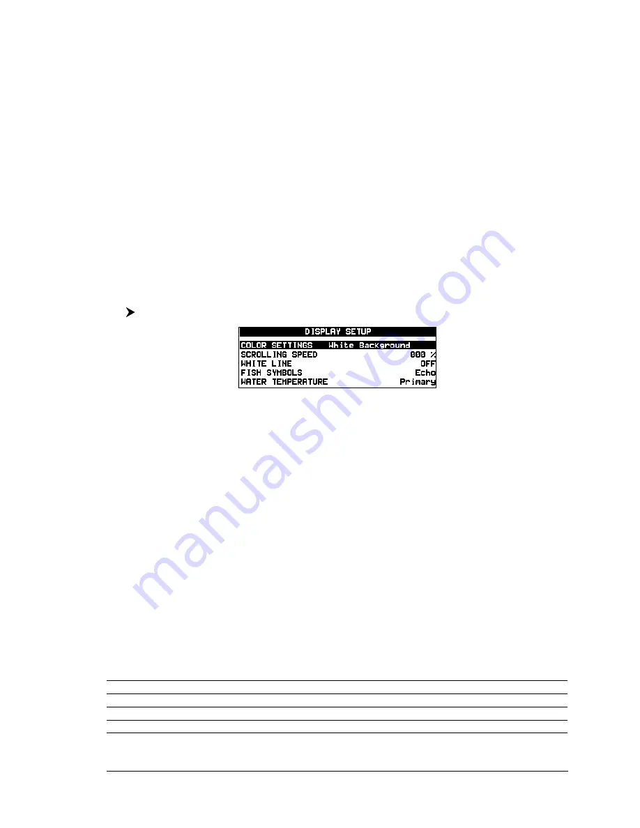
3.1.10 Display Setup

The Display Setup Menu allows you to change the color scheme of the Fish Finder

display, adjusts the chart scrolling rate, enables or disables the White Line and

allows determining the graphical representation of fish.

[MENU] + "DISPLAY SETUP" + [ENTER]

Fig. 3.1.10  -  Fish Finder Display Setup menu

3.1.10.1

Color Settings 

ONLY FOR COLOR CHART PLOTTER

Allows you to change the color scheme of the Fish Finder display. The available

colors are Blue Background, White Background, Black Background, Gray Scale

and Reversed Gray Scale.

NOTE

Only Gray Scale and Reversed Gray Scale are available on the 11" Gray Levels

chart plotters.

3.1.10.2

Scrolling Speed

Adjusts the chart scrolling rate. Note that the scrolling rate is limited by the sound

speed and the depth according with the following relation: the deeper the setting,

the slower the scrolling rate. 100% is the maximum possible.

3.1.10.3

White Line

Controls how the chart plotter displays information about the bottom type (hard

or soft).

3.1.10.4

Fish Symbols

This selection allows determining the graphical representation of underwater sus-

pended targets. See the following table.

Echo

: shows echoes

Echo + Icon

: shows the Fish icon and echoes

Echo + Icon + Depth

: shows the Fish icon, depth values and the fish echoes

Echo + Depth

: shows depth values

Summary of Contents for 50-200

Page 1: ...06 User Manual Copyright 2006 Interphase Technologies Inc All rights reserved Printed in Italy No part of this publication may be reproduced or distributed in any form or by any means or stored in a d...

Page 2: ...lay page 15 2 2 5 Chart Fish Display page 16 2 2 6 Fish Finder and Radar pages ONLY FOR CM 11CV 11 CVS 169 CS 169 CSI 16 2 3 ZOOM MODES 17 2 3 1 The Bottom Lock Zoom 17 2 3 2 The Marker Zoom 17 2 4 IN...

Page 3: ...3 3 1 12 4 Temperature Lower 23 3 1 12 5 Temperature Rate 23 3 1 12 6 Fish Alarm 23 3 1 13 Load Settings from User C CARD 23 3 1 14 Save Settings to User C CARD 23 3 1 15 Restore Current Preset Defaul...

Page 4: ...DISCLAIMS ANY AND ALL OTHER WARRANTIES INCLUDING WARRANTIES OF SUIT ABILITY OR FITNESS FOR A PARTICULAR PURPOSE IN NO EVENT WILL INTER PHASE TECHNOLOGIES INC NAVIGATION SYSTEMS LTD BE LIABLE FOR CON S...

Page 5: ...operation and function activation in this User Manual is related to all chartplotter models see the following table Whenever it is necessary a note has been inserted for those models with differences...

Page 6: ...n of the Fish Finder Setup menu CHAPTER 4 50 200 FISH FINDER Technical specification dimension and installation of the 50 200 FISH FINDER and set up of the hardware configuration CHAPTER 5 Transducers...

Page 7: ...bject When the reflected wave is returned to the transducer it is converted into an voltage and is amplified by the receiver processed and sent to the display The speed of sound in water is roughly 48...

Page 8: ...nition for devices automatic trasducer identification and parameters setup for best performance Alarms Handling Shallow Alarm Depth Alarm Fish alarm Tempera ture Upper Temperature Lower NOTE On specif...

Page 9: ...rms listed in the previous Fig 2 1 Warning Message Flashing label Simulation when the echo sounder is in Simulation mode Fish Finder Display Graphic presentation of sonar soundings recorded as a conti...

Page 10: ...the zoomed window on the left part of the screen It is turned on selecting Zoom Full display page A Scope A real time representation of fish and bottom features passing through the beam of the transd...

Page 11: ...een a hard and soft bottom and even to distinguish fish and structures located nearby the bottom For example a soft muddy or weedy bottom returns a weaker echo that is shown with a narrow white line w...

Page 12: ...er Full Display page To display the Fish Finder Full Page Display follow this procedure PAGE Full Display ENTER Fig 2 2 2 The 200kHz Fish Finder Full Display NOTE The frequency displayed depends on th...

Page 13: ...lay ENTER Fig 2 2 3 Fish Finder Dual Frequency mode The Cursor key Moving the cursor to the right or the left moves the Variable Depth Marker VDM between the 50 and 200kHz displays Moving the cursor u...

Page 14: ...the active window When in Chart Fish mode pressing MENU if the focus the active window in on the Chart the Main menu is shown Pressing again MENU opens the Fish Finder Setup menu and moves the focus...

Page 15: ...Depth Marker VDM is not displayed on the screen In Bottom Lock Zoom mode the Fish Finder Display is automatically moved up down as to keep the Bottom Line always visible in the lower half of the scree...

Page 16: ...th the desired information on the Fish Finder Library row and on the Fish Finder module row Fig 2 4 System Information page 2 4 1 The System Update menu The System Update menu allows downloading the F...

Page 17: ...equency do not change Shift 0 STC Short if Freq 200kHzandMidifFreq 50kHz ScrollingSpeed 10 FishSymbols Echo A Scope On Surface Noise Filter 4 3 1 2 Gain Mode Selects Auto or Manual MENU GAIN MODE ENTE...

Page 18: ...accessible both from the Fish Finder Setup menu and by pressing ENTER when in Fish Finder pages All settings in the Sensitivity menu are related to the Frequency selected MENU SENSITIVITY ENTER Fig 3...

Page 19: ...SPLAY SETUP ENTER Fig 3 1 10 Fish Finder Display Setup menu 3 1 10 1 Color Settings ONLY FOR COLOR CHART PLOTTER Allows you to change the color scheme of the Fish Finder display The available colors a...

Page 20: ...1 2 Calibrate Sound Speed Allows calibrating the value of Sound Speed in the water depending on the water temperature and salinity 3 1 11 3 Calibrate Water Speed Allows calibrating the value of Water...

Page 21: ...e unit switches an alarm to sound These options are Off Small Medium Big and Huge The alarm sounds if the set size or bigger is detected 3 1 13 Load Settings from User C CARD Load the complete setting...

Page 22: ...24 User Manual...

Page 23: ...Ft 299m 1KW 50kHz 5Ft 1 52m to 4000Ft 1219m Max Typical 2700Ft 823m 500W 200kHz 2 5Ft 0 76m to 700Ft 213m Max Typical 600 Ft 183m 500W 50kHz 5Ft 1 52m to 1500Ft 457m Max Typical 1350 Ft 411m NOTE This...

Page 24: ...erial and optional devices cables already connected User Manual 4 2 DIMENSIONS Fig 4 2 50 200 FISH FINDER Dimensions 4 3 MOUNTING THE FISH FINDER The 50 200 FISH FINDER should be preferably mounted in...

Page 25: ...different diagnostic conditions These are described below OFF The 50 200 FISH FINDER is running in the boot loader or DC power is not being supplied to the 50 200 FISH FINDER ON CONTINUOSLY The transd...

Page 26: ...SUPPLY WIRING DIAGRAM We recommended the installation of a switch and a 5A fuse in the positive DC supply to the 50 200 FISH FINDER The 50 200 FISH FINDER is active sending the digital depth through t...

Page 27: ...chart plotter User Manual see the following picture to make the connection to the chart plotter GND COMMON 10 35 Vdc RED BLACK OUTPUT1 INPUT2 OUTPUT2 INPUT1 INPUT1 WHITE GREEN YELLOW GRAY BROWN WIRE...

Page 28: ...30 User Manual Fig 4 7a Connection to the Fish Finder for chart plotter with 8 pin Power I O connector...

Page 29: ...and receives sound waves into the water The active component inside the transducer is commonly referred to as an element but actually is a piezoelectric ceramic material Please refer to your dealer an...

Page 30: ...32 User Manual...

Page 31: ...lowing figure Fig 6 1 The 50 200 FISH FINDER I Once the screws are removed pull out the panel and the Printed Circuit Board PCB Unscrew the cables from the PCB Fig 6 1a The 50 200 FISH FINDER II Wire...

Page 32: ...ity set tings GAIN OFFSET NOISE level and STC optimized for displaying at best the bottom FISH sets the Fish Finder in full auto mode with the sensitivity setting optimized for target searching 6 4 Ho...

Page 33: ...il When this happens the auto range algorithm also fails To recover from this situation it is necessary to switch to manual range mode and to set the manual depth mode When manual depth mode is select...

Page 34: ...at shall I do to reduce the screen clutter Try increasing the NOISE LEVEL or decreasing the GAIN OFFSET 6 15 In very shallow waters when the AUTO GAIN mode is selected there are fluctuations in the bo...

Page 35: ...10 20 K Keel Offset 22 L Load Settings from User C CARD 23 M MENU key 14 16 Mounting 27 N Noise Filter 10 34 O Operating Frequency 12 25 Output Power 25 P Page Selection menu 13 Power Consumption 25 P...

Reviews: