22
441 01 2613 05
Specifications are subject to change without notice
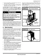
Figure 19
Electrical Connections
NOTE: 115 VAC/60Hz/single
!
phase
Operating voltage range*: 127 VAC max, 104 VAC min.
* Permissible limits of voltage at which unit will operate satisfactorily
115V. 60Hz.
W
BK
G
Connection
Box
Ground
HOT
NEUT
.
Thermostat
Low Voltage
Terminal Board
R
G
G
Y
R
Y
W
W
C
Drawing is representative some models may vary in appearance.
Furnace Control
The furnace control is preset at the factory with
ON
delay of 30
seconds in the heating mode. The blower
OFF
timing is preset at
140 seconds. If desired, the fan
OFF
delay can be reset to obtain
the longest delay times while still maintaining comfort levels. See
“Furnace Wiring Diagram”.
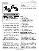
Furnace Control Fuse
The 24V circuit contains a 5
!
amp, automotive
!
type fuse located
on furnace control. (See
Figure 20
) Any electrical shorts of 24V
wiring during installation, service, or maintenance may cause fuse
to blow. If fuse replacement is required, use only a fuse of identical
size (5 amp.).
Control Connections
Figure 20
FUSE
25-24-98
Diagnostic Light
Jumper
24 VAC
HUM
115 VAC
HUM
10. Ductwork and Filter (Upflow/Horizontal)
CARBON MONOXIDE POISONING HAZARD
Failure to follow this warning could result in
personal injury or death.
Do NOT draw return air from inside a closet or utility
room where furnace is located. Return air duct
MUST be sealed to furnace casing.
!
WARNING
Duct Connections
This furnace may be installed in only a bottom or side return
!
air
duct application. Return air duct connections through the back of
the furnace is
NOT
permitted.
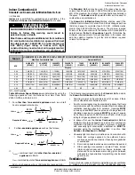
Upflow ONLY:
Side return
!
air duct connections can be made by
cutting out the embossed area shown in
Figure 21.
A knockout
hole is provided at each furnace side duct location to help start
cutting the opening. Side duct connections are NOT permitted in
horizontal flow applications.
Upflow and Horizontal Flow:
Bottom return
!
air duct
connections can be made by removing the knockout panel in the
furnace base. Do
NOT
remove knock-out except for a bottom
return
!
air duct connection.
Cutting Side Return Air Opening
Figure 21
Knockout
Starting
Hole
Duct Design
Design and install air distribution system to comply with Air
Conditioning Contractors of America manuals or other approved
methods that conform to local codes and good trade practices.
When the furnace is located in an area near or adjacent to the living
area, the system should be carefully designed with returns to
minimize noise transmission through the return air grille. Any
blower moving a high volume of air will produce audible noise,
which could be objectionable when the furnace is located very
National Excelsior Company
www.excelsiorhvac.com
Subject to change without notice.

