441 01 2613 05
27
Specifications are subject to change without notice
(
Figure 26
). Insert filter into side clips first and push filter back until
it is fully engaged into back clip.
Figure 31
Top Mounted Internal Filter
9
″
Center Clip
side-to-side
NOTE: If filters are only suitable for heating application,
advise homeowner that filter size may need to be increased if
air conditioning is added.
Addition Of Air Conditioning
See
Section 10.
12. Checks and Adjustments
Startup
NOTE:
Refer to startup procedures in the
Users Information
Manual
.
!
ELECTRICAL SHOCK, FIRE, OR EXPLOSION
HAZARD
Failure to follow this warning could result in
personal injury, death, and/or property damage.
If any sparks, odors or unusual noises occur,
immediately shut OFF gas and power to furnace.
Check for wiring errors or obstruction to blower.
WARNING
Gas Supply Pressure
Gas supply pressure should be within minimum and maximum
values listed on rating plate. Pressures are usually set by gas
suppliers.
(See Propane Gas Conversion Kit instruction manual for furnaces
converted to Propane gas.)
Manifold Gas Pressure Adjustment
NOTE:
Make adjustment to manifold pressure with burners
operating.
!
FIRE OR EXPLOSION HAZARD
Failure to follow this warning could result in
personal injury, death, and/or property damage.
Turn OFF gas at shut off before connecting
manometer.
WARNING
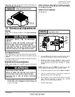
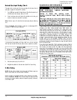
1. With gas
OFF
, connect manometer to manifold pressure tap
on outlet of gas valve. See
Figure 32
. Use a manometer with
a 0 to 12 in wc range.
Typical Gas Valve
Regulator Adjustment
Under Cap
Inlet
Pressure
Tap
1
/
8
NPT
INLET
OUTLET
Outlet
Pressure
Tap
1
/
8
NPT
IN
O
FF
ON
HONEYWELL
Figure 32
2. Turn gas
ON
. Operate the furnace by using a jumper wire on
the R to W thermostat connection on the control board.
3. Remove manifold pressure adjustment screw cover on
furnace gas valve. Turn adjusting screw counterclockwise to
decrease manifold pressure and clockwise to increase
pressure.
NOTE:
Adjustment screw cover
MUST
be replaced on gas valve
before reading manifold pressure and operating furnace.
4. Set manifold pressure to value shown in
Table 6
or
Table 7
.
5. When the manifold pressure is properly set, replace the
adjustment screw cover on the gas valve.
6. Remove jumper wire from thermostat connection on control
board. Remove manometer connection from manifold
pressure tap, and replace plug in gas valve.
7. Check for leaks at plug.
National Excelsior Company
www.excelsiorhvac.com
Subject to change without notice.


