background image

Chapter 3 — Troubleshooting

26

 Forklift Power Supply Installation Guide

Identifying and Correcting Problems

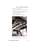
The following is an overview for troubleshooting the forklift 
power supply installation:

1

Inspect the hardware.

2

Check the electrical measurements.

3

Substitute components.

Use the procedures within this chapter to identify and the power 
supply problems you may encounter during installation. 
Connector pin-out information is also furnished for your 
convenience.

Inspecting the Hardware

Always check the hardware first. You should check the power 
supply, the cables and connections, and the fuse.

If the LED is lit, and you suspect a power failure, check the 
output cable and its connections.

If the LED is not lit, the power supply is not producing 12 Vx 
output power. In this case, a fault can exist anywhere in the 
system. Use the tables starting on page 30 to isolate, identify, 
and correct the fault.

If the LED is flickering, the power supply has detected a fault 
condition related to temperature, voltage, or current. The 
LED will flicker until the problem is resolved. In some cases, 
you may have to remove power to reset the power supply.

Checking the Electrical Measurements

You can measure the voltage or test for continuity to 
troubleshoot the battery cable.

Measuring the Voltage

Connector pinout information is provided to allow you to 
measure voltage at the input power cable connector and at either 
end of the power output cable.

Performing Continuity Testing

Thorough continuity testing takes longer than either 
substitution or taking voltage measurements. An ohmmeter is 
sufficient to diagnose simple opens or shorts.

Summary of Contents for 203-880-002

Page 1: ...Forklift Power Supply Installation Guide...

Page 2: ...e and do not represent a commitment on the part of Intermec Technologies Corporation 2008 2009 by Intermec Technologies Corporation All rights reserved The word Intermec the Intermec logo Norand ArciT...

Page 3: ...ge Record This page records changes to this document The document was originally released as Revision 001 Version Number Date Description of Change 002 6 2009 Updated to include new printer models and...

Page 4: ...iv Forklift Power Supply Installation Guide...

Page 5: ...ines 2 Power Supply Considerations 3 Understanding Power Supply LEDs 3 Using the Input Power Cable 4 Using the Inline Fuse 5 Using the Output Power Cable 6 Contents of the Forklift Power Supply Kit 6...

Page 6: ...Ends 18 Connecting to the Forklift Battery 19 Connecting to Side Mount Battery Terminals 19 Connecting to Top Mount Battery Terminals 20 Securing the Battery Cable 21 Connecting the Output Power Cable...

Page 7: ...Contents Forklift Power Supply Installation Guide vii...

Page 8: ...tions and notes that are in this document Global Services and Support Warranty Information To understand the warranty for your Intermec product visit the Intermec web site at www intermec com and clic...

Page 9: ...mec technical knowledge base Knowledge Central at www intermec com and click Support Knowledge Central to review technical information or to request technical support for your Intermec product Telepho...

Page 10: ...nsible for installing configuring and maintaining the Forklift Power Supply The Forklift Power Supply Installation Kit can be used with the PB21 PB22 PB31 PB32 PB50 PB51 and PW50 mobile printers This...

Page 11: ...e forklift power supply that is used for your mobile printer This chapter contains these topics Understanding the DC Power Supply Kit Installation Guidelines Power Supply Considerations Contents of th...

Page 12: ...t where this kit is installed You should also be trained and experienced in forklift electrical systems Follow these guidelines and the installation procedures as well as those of the lift manufacture...

Page 13: ...wer supply produces heat Intermec advises that you mount it on a metallic surface that is a minimum of 838 to 1032 square cm 130 to 160 square inches which is approximately one square foot or more to...

Page 14: ...s on attaching the power cable see Mounting the Power Supply on page 11 Note If the secondary LED is not lit the input power to the DC DC converter is less than 9 to 10 Vx It will continue to provide...

Page 15: ...batteries For other vehicle battery voltages please refer to the table below These alternate fuses are not provided with the kit and must be obtained separately In general smaller fuse ratings offer f...

Page 16: ...ment For a diagram of the output cable see the next section Contents of the Forklift Power Supply Kit Installing the Printer With the Forklift Power Supply Kit Note Ensure that you have the correct ou...

Page 17: ...8 flat washer 803 084 000 1 Snap in bushing 807 065 003 1 Screw 1 4 20 x 1 1 4 inch 801 194 002 2 Flat washer 803 100 001 2 Locking nut 802 117 000 2 Washer split lock 803 042 001 2 Cable tie locking...

Page 18: ...s a reference during the planning phase of your power supply installation Power Source Connection Possibilities Distribution panels work better than direct connect to motors Power Acceptable Negative...

Page 19: ...forklift power supply This chapter contains these topics Installation Recommendations Preparing the Power Input Cable Mounting the Power Supply Installing the Input Power Cable Connecting the Power Ca...

Page 20: ...nnector Design a bracket that would be common to multiple lifts with pre attached devices to simplify the device installation and service Designing a common bracket would reduce your installation time...

Page 21: ...able Use these directions to attach the input cable connector to the power supply To connect the power input cable 1 Attach the input cable connector P N 226 340 004 to the power supply P N 851 070 00...

Page 22: ...w of Negative and Positive Direct Versus Isolation Mounting on the Lift Chassis Previously the power supply was placed directly on the lift chassis Direct mounting provides both an adequate heat sink...

Page 23: ...ashers or rubber isolators or an insulating surface plastic wood or rubber between the power supply and lift chassis Mounting the power supply on a metal plate also requires a small resistor 100 ohms...

Page 24: ...lation To use mounting Method A 1 Mark and center punch the two mounting holes on the mounting surface 2 Use a 1 4 inch drill bit to make the two mounting holes 3 Use 1 4 inch hex bolts with flat wash...

Page 25: ...physically and electrically as possible to the positive side of the forklift power source The remaining colored wires must be connected to the negative side of the forklift power source If this instal...

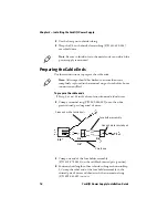
Page 26: ...strip the individual wire ends of the cable as instructed 2 Slip heat shrink tubing furnished in this kit onto the cable or wires before terminating them 3 Prepare the cable ends by installing the fus...

Page 27: ...21 050 003 for the shield wire To install heat shrink tubing 1 Crimp terminal rings and fuse holder ends then position all heat shrink tubing in the locations shown Red and black wires positive Shield...

Page 28: ...f wires 3 Crimp one end of the fuse holder assembly P N 315 075 0013 on the red black twisted pair positive 4 Position short lengths of heat shrink tubing as shown in Step 2 Crimp the other end of the...

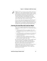
Page 29: ...ttach the forklift battery cable to a side mount battery terminal To connect the forklift battery cable to a side mount battery terminal 1 Disconnect the negative battery cable then disconnect the pos...

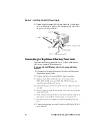
Page 30: ...the positive battery cable 2 Remove the bolts from the forklift battery terminals 3 Replace those bolts with 3 8 inch x 1 1 2 inch bolts P N 800 099 001 and nuts P N 802 099 001 from the installation...

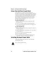
Page 31: ...ch using locking wire ties or adjustable cable clamps To install cable clamps 1 Remove the paper backing from the clamp P N 808 011 001 and stick the clamp in place 2 Drill a pilot hole with a 26 dril...

Page 32: ...C power supply P N 851 070 003 3 Slide the output cable as far as it will go into the power supply 4 Turn the output cable connector collar clockwise to secure it 5 After all connections are secure co...

Page 33: ...components LED visibility is good power cables are out of the way and tied off there is adequate heat sink and there is good access for cooling good access for component service full access to the UP...

Page 34: ...rating temperature A poorly planned installation presents several challenges including Difficult access to power supply components LED visibility in operation is impossible Damage could occur to lift...

Page 35: ...25 3 Troubleshooting This chapter contains information for troubleshooting the forklift power supply This chapter contains these topics Identifying and Correcting Problems Troubleshooting Charts...

Page 36: ...lit the power supply is not producing 12 Vx output power In this case a fault can exist anywhere in the system Use the tables starting on page 30 to isolate identify and correct the fault If the LED i...

Page 37: ...ting charts substituting only when directed to do so If an installation suffers intermittent input power fuse failures or if the power supply shuts down without good cause do not hesitate to substitut...

Page 38: ...rating for the power supply Work with your forklift manufacturer to look for alternate power connection locations Check to see whether they have any recommended inline filters or suppressors Flickers...

Page 39: ...le if input voltage is still not present at connector The fuse is blowing but no LED is lit Power system is drawing too much current Have the forklift vendor recommended an inline filter and alternate...

Page 40: ...P N 226 340 004 Secondary output power connector heater Pin1 Pin2 Main output power connector Pin 3 Pin 2 Pin 1 Power Supply Pinouts continued Connector Negative Positive Case 108 0 3 0 2 1 Pin view P...

Page 41: ...ation Guide 31 Note The cables in the installation kit may contain alternate wire colors Refer to the following chart for the wire color equivalent Cable Wire Cable Equivalents Wire Color Alternate Co...

Page 42: ...Chapter 3 Troubleshooting 32 Forklift Power Supply Installation Guide...

Page 43: ......

Page 44: ...36th Avenue West Everett Washington 98203 U S A tel 425 348 2600 fax 425 355 9551 www intermec com 2009 Intermec Technologies Corporation All rights reserved Forklift Power Supply Installation Guide...

Reviews: