User’s Manual of NS3550-24T/4S
129
VLAN 3: Port-4, Port-5 and Port-6
VLAN 1: All other ports – Port-7~Port-24
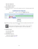
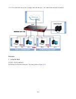
About the VLAN ports connect to the hosts, please refer to 4.6.10.1 examples. The following steps will focus on the VLAN
Trunk
port
configuration.
1. Specify
Port-8
to be the 802.1Q VLAN
Trunk port
.
2. Assign
Port-8
to both
VLAN 2
and
VLAN 3
at the VLAN Member configuration page.
3. Define
a
VLAN 1
as a
“Public Area”
that overlapping with both
VLAN 2 members
and
VLAN 3 members
.
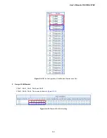
4. Assign the VLAN Trunk Port to be the member of each VLAN – which wants to be aggregated. At this sample, add
Port-8
to
be
VLAN 2
and
VLAN 3
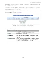
member port. The screen is shown in
Figure 4-6-12.
Figure 4-6-12
VLAN Overlap Port Setting &
VLAN 1 – The Public Area Member Assign
5. Specify
Port-8
to be the 802.1Q VLAN
Trunk port
, and the Trunking port must be a
Tagged
port while egress. The Port-8
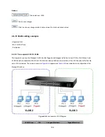
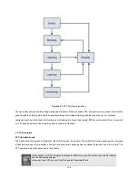
configuration as the following screen is shown in
Figure 4-6-1
3
.
Figure 4-6-13
The Configuration of VLAN Trunk port
That is, although the VLAN 2 members: Port-1 to Port-3 and VLAN 3 members: Port-4 to Port-6 also belongs to VLAN 1. But with
different PVID settings, packets form VLAN 2 or VLAN 3 is not able to access to the other VLAN.
6. Repeats Step 1 to 5, setup the VLAN Trunk port at the partner switch and add more VLANs to join the VLAN trunk, repeats
Step 1 to 3 to assign the Trunk port to the VLANs.
4.6.10.3 Port Isolate
The diagram shows how the Managed Switch handles isolate and promiscuous ports, and the each PCs are not able to access
each other PCs of each isolate port. But they all need to access with the same server/AP/Printer. The screen is shown in
Figure
Summary of Contents for IFS NS3550-24T/4S
Page 1: ...P N 1072569 REV 00 05 ISS 11OCT12 IFS NS3550 24T 4S User Manual ...
Page 37: ...User s Manual of NS3550 24T 4S 37 ...
Page 96: ...96 Figure 4 4 6 Port Mirror Configuration Page Screenshot ...
Page 127: ...User s Manual of NS3550 24T 4S 127 Figure 4 6 10 Port 1 Port 6 VLAN Configuration ...
Page 184: ...184 Figure 4 9 14 Voice VLAN Configuration Page Screenshot ...
Page 204: ...204 Figure 4 11 4 Network Access Server Configuration Page Screenshot ...
Page 234: ...234 Figure 4 12 1 Port Limit Control Configuration Overview Page Screenshot ...
Page 250: ...250 Click to undo any changes made locally and revert to previously saved values ...
Page 297: ...User s Manual of NS3550 24T 4S 297 ...
Page 388: ...388 Example Show RADIUS statistics SWITCH security aaa statistics ...
Page 410: ...410 Parameters vid VLAN ID 1 4095 Default Setting disable ...


