background image


load.UP manual, page 9 

©


InterCard GmbH Kartensysteme


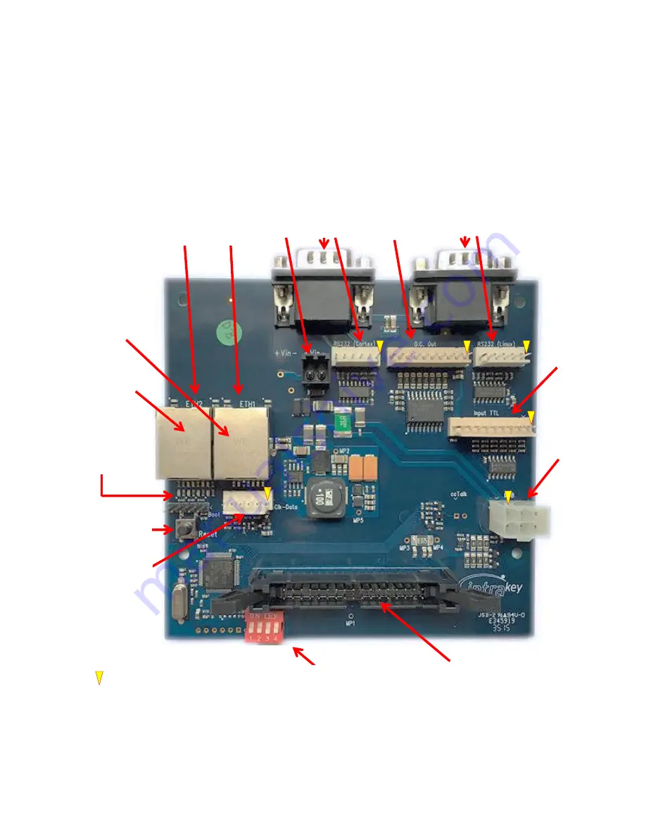
load.UP Connector Board


Note:


Do not refer to this illustration for touch.ON support; the boards are different and also require different 

firmware
 

Dispenser


Printer 

24V


+  - 

Network 

port 1 

Network 

port 2 

Open collector 

LED drivers 

General 

purpose 

inputs 

MDB 

Coprocessor 

reset 

Connection 

to main 

board 

Designates pin 1 

Mag card 

clock & data  

Not currently used 

           LEDs 
Blue – Bill MDB 
Red – Coin MDB 
Green – Credit Card 
Yellow – Heartbeat 
 

Green LED - Link 
Yellow LED - activity 

Summary of Contents for load.UP

Page 1: ...InterCard Villingen Schwenningen Germany load UP Account loader Product Guide...

Page 2: ...parameters screen Network settings System settings Page 5 Locale setting Card readers Card testing Page 6 Display menu Welcome screen Meters About screen Page 7 Paper replacement Internal components W...

Page 3: ...al order Coin acceptor changer Your load UP may be ordered with an electronic coin mechanism capable of validating up to six coin values Bank card terminal For secure payment by debit credit card fees...

Page 4: ...te Read only in DHCP mode Gateway IP IP of local network s Gateway Read only in DHCP mode You must reboot the load UP for changes to take effect System Screen Here you can activate four cumulative log...

Page 5: ...ge return It s important to note that the load UP does not alter in any way the data read from USB card readers So when setting up programmable readers it s important the output string look like the a...

Page 6: ...ad of the standard InterCard welcome screen If you d like to make your own welcome screen use the settings below and use the web interface to load the screen into the load UP Dimensions 640 x 480 File...

Page 7: ...ler and close the black paper lid the printer should detect the paper and auto feed If not press the LF button on the side of the printer to pull it through Internal Components 1 Touch Screen Display...

Page 8: ...is plugged into to 110V or 220V and is powered up 2 Verify that you have a network link by checking the green link LED located a couple of mm from where the network cable plugs into the board You can...

Page 9: ...ifferent and also require different firmware Dispenser Printer 24V Network port 1 Network port 2 Open collector LED drivers General purpose inputs MDB Coprocessor reset Connection to main board Design...

Reviews: