background image

6

General Installation Process

2.5" HDD

d3

d4

2.5" HDD

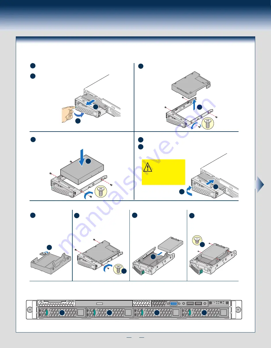
Install Hard Drives ...continued

3.5" Hard Drive Carrier (For system with 3.5" hard drive bay only)

Hard Drive Numbering Diagram

Drive 0 Primary

A

B

Remove the drive carrier by pressing the 

green

 button and opening 

the lever. 

E
F

Slide the carrier out.

TOP

BREAK OFF T

AB

BEFORE MOUTING

2.5´´ HARD DRIVE

C

Remove the four screws securing the HDD interface bracket and remove 

the HDD interface bracket

.

Install 2.5” Hard Drive as option:

3.5´´ HDD

D

D

Install the hard disk drive using the same four screws as shown. Make 

sure the connector end of the drive matches the backplane connector.

With the lever open, insert the hard disk drive assembly into the chassis.

Push in the lever to lock it into place.

4 x 3.5” hard drive bay as shown

CAUTION:  

If you do not 

install all drives, empty drive 

bays must be occupied by 

carriers with plastic drive 

blank provided to maintain 

proper system cooling.

d1

d4

d2

d3

Install the HDD interface bracket 

from top. Secure the bracket with 

three screws as shown.

Slide the 2.5” HDD into the 

bracket to align the screw holes 

with the right and the left rail.

Break off the tab on the 

HDD interface bracket

.

Secure the hard disk drive using 

the four screws for 2.5” HDD

.

d1

Bottom 

View 

TOP

BREAK OFF T

AB

BEFORE MOUTING

2.5´´ HARD DRIVE

d2

TOP

BREAK OFF T

AB

BEFORE MOUTING

2.5´´ HARD DRIVE

A

B

F

E

0

1

2

3

C

Summary of Contents for R1000SP

Page 1: ...stall components If you are not familiar with ESD ElectroStatic Discharge procedures used during system integration see the complete ESD procedures described in your Service Guide This guide and other...

Page 2: ...This page is intentionally left blank...

Page 3: ...ard Riser Assembly 7 Install Add in Card 7 Install Add in Card Riser Assembly 8 Install Rack Handles 8 Install Intel I O Expansion Module optional 8 Install Intel RAID C600 Upgrade Key optional 8 Inst...

Page 4: ...k of Intel Corporation or its subsidiaries in the United States and other countries Other names and brands may be claimed as the property of others Copyright 2012 Intel Corporation All rights reserved...

Page 5: ...Supply Hard Drive Bays Front Control Panel System Features and Components 3 5 Hard Drive Bay system as shown Useful Information The SCU1 4 7 port requires an Intel RAID C600 Upgrade Key installed to...

Page 6: ...oard connections or install components 3 Remove the Air Duct Remove the air duct by lifting straight up IMPORTANT Before proceeding further check your Intel Server System for disconnected or loose cab...

Page 7: ...with the two orientation posts on the socket A Install the processor as shown Orientation Posts Orientation Notches A A B C Close the load plate all the way as shown Install the Processor continued Ca...

Page 8: ...s screwdriver start with screw 1 and engage screw threads by giving it two rotations and stop Do not fully tighten Proceed to screw 2 and engage screw threads by giving it two rotations and stop Simil...

Page 9: ...Primary 8 x 2 5 hard drive bay as shown A B Remove the drive carrier by pressing the green latch to unlock Pull out the black lever and slide the carrier out Remove the four screws securing the plasti...

Page 10: ...of the drive matches the backplane connector With the lever open insert the hard disk drive assembly into the chassis Push in the lever to lock it into place 4 x 3 5 hard drive bay as shown CAUTION If...

Page 11: ...e optical device bay filler panel shown below This is required to maintain proper system cooling Rear View of Optical Drive A Install the plastic guide onto the back of the drive and attach with two s...

Page 12: ...n e c t o r 17 Install Intel Remote Management Module 4 optional A d d i n C a r d Slots Hooks 13 Install Add in Card Riser Assembly Position the riser card edge connector over the server board riser...

Page 13: ...stall Intel RAID Smart Battery optional A B A Locate the BBU bracket inside the chassis Align the tabs on the plastic battery holder with mounting holes on the BBU bracket B Slide the plastic battery...

Page 14: ...rating system running insert the Intel Server Deployment Management DVD If using a Microsoft Windows operating system the Express Installer will autorun and allow you to select the appropriate drivers...

Page 15: ...U FAN Main Power PS AUX Slot 6 PCI e_x16 RMM4 LITE TPM DIMM_C2 DIMM_C1 DIMM_B2 DIMM_B1 DIMM_A2 DIMM_A1 SYS FAN_3 SYS FAN_4 SYS FAN_1 SYS FAN_2 SYS FAN_5 CPU Power USB 4 5 LCP SCU 0 Jumper Blocks SCU 1...

Page 16: ...N 5 FAN 1 FAN 2 Fixed System Fans Redundant System Fans 1 2 3 4 Air Flow Air Flow 1 2 3 4 5 A complete list of accessories and spares can be found at http www intel com p en_US support post production...

Page 17: ...ard drive bay System Cabling Diagram 3 5 SATA HDD 7 Pin SATA 1x5 Pin SATA Pwr 3 5 SATA HDD 7 Pin SATA 1x5 Pin SATA Pwr 3 5 SATA HDD 7 Pin SATA 1x5 Pin SATA Pwr 3 5 SATA HDD 7 Pin SATA 1x5 Pin SATA Pwr...

Page 18: ...nel USB FAN 1 FAN 2 SCU 0 PS AUX CPU Power SATA 1 SYS FAN_1 SYS FAN_2 SYS FAN_3 SYS FAN_4 SYS FAN_5 Intel Integrated RAID Module BBU Note To activate the port SCU1 4 7 on the server board a proper Int...

Page 19: ...U Power SATA 1 Power Supply 450W SYS FAN_1 SYS FAN_2 SYS FAN_3 SYS FAN_4 SYS FAN_5 Intel Integrated RAID Module BBU Note To activate the port SCU1 4 7 on the server board a proper Intel RAID C600 Upgr...

Page 20: ...G64256 003...

Reviews: