background image

A

-

0

0

1

2

r

o

f

s

n

o

i

t

p

O

g

n

i

g

n

a

R

6

1

n

o

i

t

p

O

h

t

i

w

d

e

i

l

p

p

u

S

O

t

u

O

e

u

g

o

l

a

n

A

O

A

S

M

M

O

C

C

l

p

p

u

S

r

e

w

o

P

y

)

4

(

S

P

d

r

a

o

B

y

r

o

m

e

M

E

M

-

0

0

1

2

E

M

A

m

0

2

~

4

1

A

2

3

2

S

R

2

3

2

)

1

(

c

d

/

c

a

V

4

6

2

~

5

8

H

r

e

d

n

a

p

x

E

y

a

l

e

R

6

1

2

R

-

0

0

1

2

2

R

A

m

0

2

~

0

2

A

2

2

4

S

R

2

2

4

c

d

V

0

9

~

3

2

M

d

B

e

v

a

l

S

y

a

l

e

R

2

2

L

R

-

0

0

1

2

2

L

R

V

0

1

~

2

1

V

5

8

4

S

R

5

8

4

c

d

/

c

a

V

8

2

~

0

1

L

s

n

o

i

t

p

O

o

N

N

V

0

1

~

0

2

V

t

e

n

r

e

h

t

E

T

E

N

16 Universal Analogue Inputs.

4 Digital Inputs. 2 Analogue

Outputs. 2 Relay Output.

INTECH Micro
2100-A

16 Rev 1.3

Features.

z


16 Universal Analogue Inputs.

z


Each Input Individually Selected & Scaled.


z


16 Bit Resolution.

z


I

nput

s

 for

:

z


RTD: 0~25C to -200~850C.


z


mV: 0~25mV to ±500mV.


z


V: 0~1V to ±15V.

z


mA: 0~1mA to ±100mA.

z

z

z

z

z

2 Analogue Ouputs.

z

z

z

z

z

Four Digital, Isolated, Optocoupler Inputs.

z

z

z

z

z

Two Digital, Isolated, Relay Outputs.

z

z

z

z

z

RS422/RS485 Up to 1200m.

z

z

z

z

z

RS232 Cost Effective Radio Installation.

z

z

z

z

z

RS232 Cost Effective PC or PLC AI Expansion.

z

z

z

z

z

Modbus RTU and Modbus TCP Options Available.

z

z

z

z

z

Clock/Reset Drive up to Four 2100-Ms.

z

z

z

z

z

Selectable Baud Rates.

z

z

z

z

z

Digital Inputs:

- State or Count.
- Speeds to 50Hz.

z

z

z

z

z

Interface for 2100-R2 (16 Relays) or 2100-ME (Memory).

z

z

z

z

z

Easy Programming Via Microscan Maps.

z

z

z

z

z

Programmable Station Number.

z

z

z

z

z

Programmable Relay States - NO or NC.

z

z

z

z

z

Comms Failure Time-out Using Relay 2.

z

z

z

z

z

Comms TXE and TX Delay Programming.

z

z

z

z

z

Programming Information Retained on Power Down.

z

z

z

z

z

Universal AC/DC Power Supply.

z

z

z

z

z

Easy to Install.

z

z

z

z

z

Compact DIN Rail Mount Enclosure

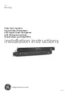
Ordering Information.

2100-A

16 Rev1 

-X

Standard Unit: Analogue Inputs Pt100, 0~100C; Analogue Outputs,

4~20mA; RS485 Comms; 

85~264Vac/dc Power Supply.

2100-A

16 Rev1

O     AO     C

PS

Quality Assurance Programme.

The modern technology and strict procedures of the ISO9001 Quality Assurance Programme applied during design,
development, production and final inspection grant long term reliability of the instrument. This instrument has been
designed and built to comply with EMC and Safety Standards requirements.

Ordering Examples.

1/ 2100-A

16

-ME-A1-232-L

2100-A

16

; Memory Board Fitted; 4~20mA AO; RS232 Comms; 10~28Vac/dc PS.

2/ 2100-A

16

-N-V2-485-H

2100-A

16

; 0~10V AO; RS485 Comms; 85~264Vac/dc Power Supply.

14.02-3

Note 1. The RS232 Comms. version comes complete with a RS232 kit, required for connecting the 2100-A

16

 to a PC,

etc. The kit contains: 1 x 5m RS232 cable; (2,10 & 15m available.) 1 x 9 pin D type (25 pin D type available).

Note 2: The 2100-A

16

 is factory set to RS232 or RS422/485. The 2100-A

16

-X is field selectable for RS422 or RS485,

and H or M power supply.

Note 3: The Microscan, PLC Message and Modbus RTU Comms Protocols come standard on all units.
Note 4:  Power supply ‘H’ is field selectable for ’M’, and ‘M’ for ‘H’. Power supply ‘L’ must be ordered separately.

2100 models include:
2100-4S : RS422 to RS485 Converter.
2100-A

16

 :16AI, 4DI, 2 Relay Out, 2 AO.

2100-A4 :4AI, 4DI, 4 Relay Out, 2 AO.
2100-A4e :4AI, 4DI, 8 Relay Out, 2 AO.
2100-AO :8 AO, 8 AI, 12 DI, 2 Relay Out.
2100-D :12DI, 12 Relay Out.
2100-IS :Isolated RS232 to RS422/485.
2100-M :16AI Multiplexer.
2100-ME :Memory Expansion for 2100-A.
2100-NET :Isolated Ethernet to RS232/422/485.
2100-NS :Non-Isolated RS232 to RS422/485.
2100-R2 :16 Relay Expansion for 2100-A.
2100-RL2 :2 Relay Expansion for 2100-A.

TECHNOLOGY

& QUALITY

A

W

A

R

D

Z985

ISO9001

E

G

IS

T

E

R

R E

D

M

ANU A T

U

R

E

R

C

F

Summary of Contents for 2100-A16

Page 1: ...INTECH Micro 2100 A16 REV 1 3 Installation Guide 14 01 1 TECHNOLOGY QUALITY A W A RD ISO9001 E G ISTE R RE D M ANU A T U R E R C F Z985...

Page 2: ...nnection Page 12 2100 ME Memory Expansion Page 12 2100 R2 Relay Expansion Page 13 RS485 Serial Connection Page 14 RS422 Serial Connection Page 14 RS232 Serial Connection Page 15 RS232 Radio Modem Seri...

Page 3: ...asy to Install z z z z z Compact DIN Rail Mount Enclosure Ordering Information 2100 A16 Rev1 X Standard Unit Analogue Inputs Pt100 0 100C Analogue Outputs 4 20mA RS485 Comms 85 264Vac dc Power Supply...

Page 4: ...t note 3 Mineral Insulated Thermocouples With Isolated Junction Essential Cold Junction Comp 0 60C CJC Drift 0 03C C Typical for Input 1 Refer to notes under 2100 A16 Input Connection Diagram for T C...

Page 5: ...for 1min General Specifications Unless otherwise stated in other input specifications Accurate to 0 1 FSO Typical Linearity Repeatability 0 1 FSO Typical Channel Separation 0 1 FSO Typical Ambient Dri...

Page 6: ...B A B B A B B A B B A B B A B B A B B AO COM AO 1 AO 2 Relay COM Relay 1 Relay 2 DI COM DI 1 DI 2 DI 3 DI 4 H3 EXPANSION CONNECTOR J9 J10 J11 J12 J13 J14 J15 J16 J1 J2 J3 J4 J5 J6 J7 J8 H1 SUPPLY VOL...

Page 7: ...i e c e r s i n o i t a t S n e h w e v i t c A X T a t a d l a i r e s g n i t t i m s n a r t s i n o i t a t S n e h w y l n o e v i t c A E X T a t a d t i m s n a r t o t y d a e r s i n o i t a...

Page 8: ...sing a clean voltage free field contact Note 4 All cables must be screened and the screens earthed at one end only Note 5 Voltage free contact values must be brought in through tags in the Scada Softw...

Page 9: ...6 The mounting orientation of the 2100 A16 eg vertical or horizontal affects the CJC accuracy of different inputs The affects are more noticeable on small temperature ranges For example mounting the 2...

Page 10: ...relay can be configured for a Normally ON or Normally OFF output state E g for fail safe operation The Normally ON OFF settings are retained in software on power down but the relays are de energized...

Page 11: ...1 61 AO 2 62 2 1 5 4 8 7 Fourth 2100 M 51 COM 53 Iout 60 CS COM 61 RESET 62 CLOCK 11 10 EXPO 3 26 COM 28 Iout 29 CS COM 30 RESET 31 CLOCK OR The analogue output mode is set in the Station Advanced Di...

Page 12: ...Protective enclosure only to be opened by qualified personnel Remove ALL power sources before removing protective cover 14 02 12 2100 A16 Connection Example Diagram for Using the 2100 RL2 2 Relay Slav...

Page 13: ...nt device Both units must be powered and unpowered at the same time to prevent indeterminate relay states 2100 A16 Rev1 3 Relay Output Expansion Using 2100 R2 Relay Expansion Output relay expansion is...

Page 14: ...ration 24 23 21 22 1 Shimaden SD20 with RS422 option 3 9 5 Shimaden SR253 with RS485 option 2100 A16 Remote Station 70 71 72 73 74 IMPORTANT i All cables must be screened ii All screens must be connec...

Page 15: ...me a unique station number before using the programme setup button in the Scada Software Requires Microscan Version 4 02 onwards For detailed programming info refer to Programming 2100 Series Remote S...

Page 16: ...TX delay is zero the data is sent immediately upon receiving a command RX The period is specified in TXE units of 2 5ms i e 10units 25ms TX TXE delay TX delay 2100 A16 Delay Settings Table Mode 3 210...

Page 17: ...e Scada COMMS allowing a PLC to read back data that the Scada will be showing Note 8 Digital inputs and digital outputs are not available in this mode 2100 A16 58 57 56 55 54 62 61 60 48 49 Bin SWITCH...

Page 18: ...as an Intelligent Multiplexer Connection Example 1 Connection of a 2100 A16 to a PLC with open collectors commoned to 24V of an external power supply PLC Input Module Analogue Input No 1 Analogue Inp...

Page 19: ...can be connected in this configuration provided the open collectors can handle the load For Binary Channel Selection the resistor 2 2k Up to two 2100 A16 can be connected in this configuration provid...

Page 20: ...ithout notification 2100 A16 Rev 1 PLC RTX Fail Safe System The PLC uses one channel of the 2100 A16 to verify that the A16 is reading the channel correctly AO1 is working and the clock and reset BCD...

Page 21: ...umper Settings Note 2 The retransmission modes of AO1 AO2 canbeusedwhentheModbusRTUprotocol is used Note 3 Rev 1 3 ONLY s e s s e r d d A l i o C l i o C x x 0 0 0 t u p u O l i o C x x 0 0 0 t u p u...

Page 22: ...0 0 3 F F F 0 0 0 t i B 2 1 6 1 t u p n I 3 x u M 7 3 0 0 3 s d r o W 2 4 5 7 E E E I 1 1 t u p n I 7 9 0 0 3 F F F 0 0 0 t i B 2 1 1 t u p n I 4 x u M 9 3 0 0 3 s d r o W 2 4 5 7 E E E I 2 1 t u p n...

Page 23: ...en inputs is 4 channels second Channels that are not scanned can be disabled via the station programming dialog boxes To speed up operation for multiplexer mode set the Scan Mode on the advanced dialo...

Page 24: ...the sockets operations You may need to open the IP address and port numbers for the commands to go through We have found problems with Nortons system Works 2003 and found it necessary to disable emai...

Page 25: ...have minimum free air space of 20mm Foreign matter must not enter or block the draft holes 3 Do not subject to vibration or excess temperature or humidity variations 4 Avoid mounting in cabinets with...

Page 26: ...lve motors this may help to stabilise the input signal Use caution when doing this as unless the inputs are at the same potential large earth currents will flow through the 0V rail causing errors on A...

Page 27: ...2 Once the above conditions have been met and the wiring checked apply power to the 2100 A16 the loops sensors 2100 Rs and 2100 Ms Allow a 5 minute warm up period longer for thermocouples refer to Inp...

Page 28: ...not be air or gas tight 3 Check cables entering the RTD sensor head Thermocouple Inputs 1 Repeat 4 of commissioning Do it regularly at least once a month 2 Replace defective protection tubes even if...

Reviews: