21
3.
Locate the CMOS clear jumper on the motherboard.
4.
Move the jumper cap from the default pins 1-2 to pins 2-3.
5.
Plug in the power cable and power on the server, and then wait for 10 seconds for
the CMOS to clear.
6.
Power down the server, unplug the power cable, and then wait for 5 seconds
again.
7.
Move the jumper cap back to the default pins 1-2.
8.
Reconnect the power cable and power on the server.
3.5
System Layout
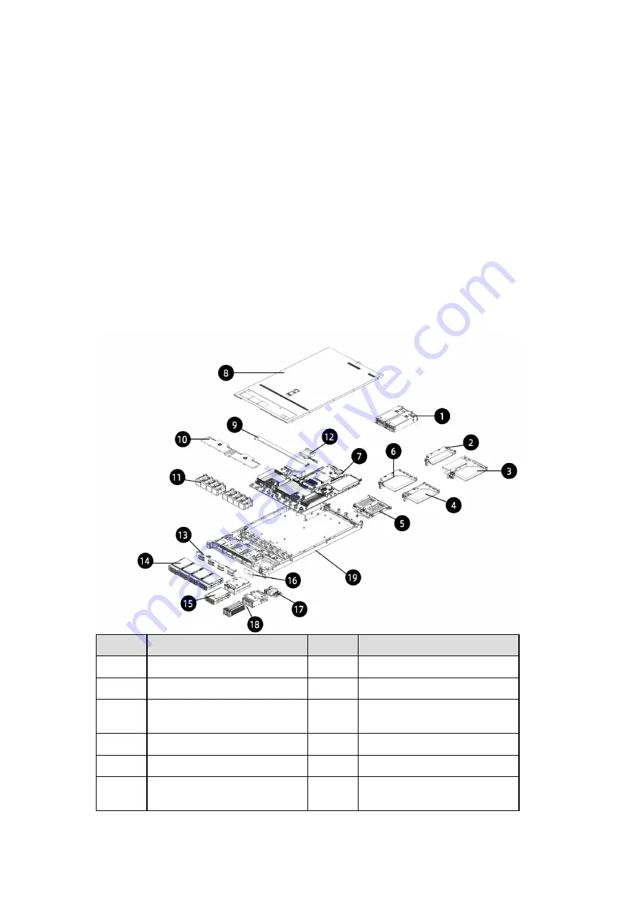
The layouts of systems with 2.5-inch and 3.5-inch drives are as below:
Figure 3-13 System Layout with 2.5-inch Drives
#
Item
#
Item
1
PSUs
11
Fan Module
2
LP PCIe
12
Super-Capacitor
3
Butterfly PCIe
13
Front 2.5-inch Drive
Backplane
4
Right PCIe Module
14
Front 2.5-inch Drive Module
5
Rear 2.5-inch Drive Module
15
Front 2.5-inch Drive Module
6
Left PCIe Module
16
Front 2.5-inch Drive
Backplane


