Inovance CV800 Series User Manual Download Page 19

M8292 

0: CANRX command 
received or idle 
1: CANRX command 
receiving state 

D8292 

The length of data 
received by CANRX 

M8293 

CANTX command 
failed to be sent 

D8293 

Reserved 

M8294 

CANRX command 
received 

D8294 

Reserved 

 
M8298 

0: CANTX command 
sent or idle 
1: CANTX command 
send state 

 
D8298 

Reserved 

M8299 

CANRX command 
receipt timeout 

D8299 

CANTX timeout 
setting (ms) 

 
CANTX/CANRX  command  is  designed  to  facilitate  communication  between  user  and  equipment  of 
third  party  with  CAN  communication  function.  With  the  command,  users  may  write  any  CAN 
communication user protocol. 
 
Format of command is as follows, 

CAN data sending 
command


CANTX [ S1 S2 D n ]


CAN data sending 
command


CANRX [ S1 S2 D n ]


S1, S2: CAN address is made up of the two parameters;   
The  bit15  and  bit14  of  S1  are  retained,  bit13  of  S1  is  for  setting  CAN  address  size,  where  "0" 
represents standard CAN address (11 bits), "1" represents extended CAN address (29 bits). An 11-bit 
address should be represented by bit0~bit10 of S2, S1 is 0 and S2 is not greater than H7FF. A 29-bit 
address  should  be made  up  by  S2 (low  16  bit  address)  and  bit0~bit12  of  S1 (high  13  bit  address), 
where bit13 of S1 is 1. 
D: D refers to send buffer in CANTX command, receive buffer in CANRX command; the maximum four 
D components that start with the D component are used as the send or receive buffer. 
n: n refers to number of data sent in CANTX command, number of data received in CANRX command; 
the maximum number of bytes is 8. 
 
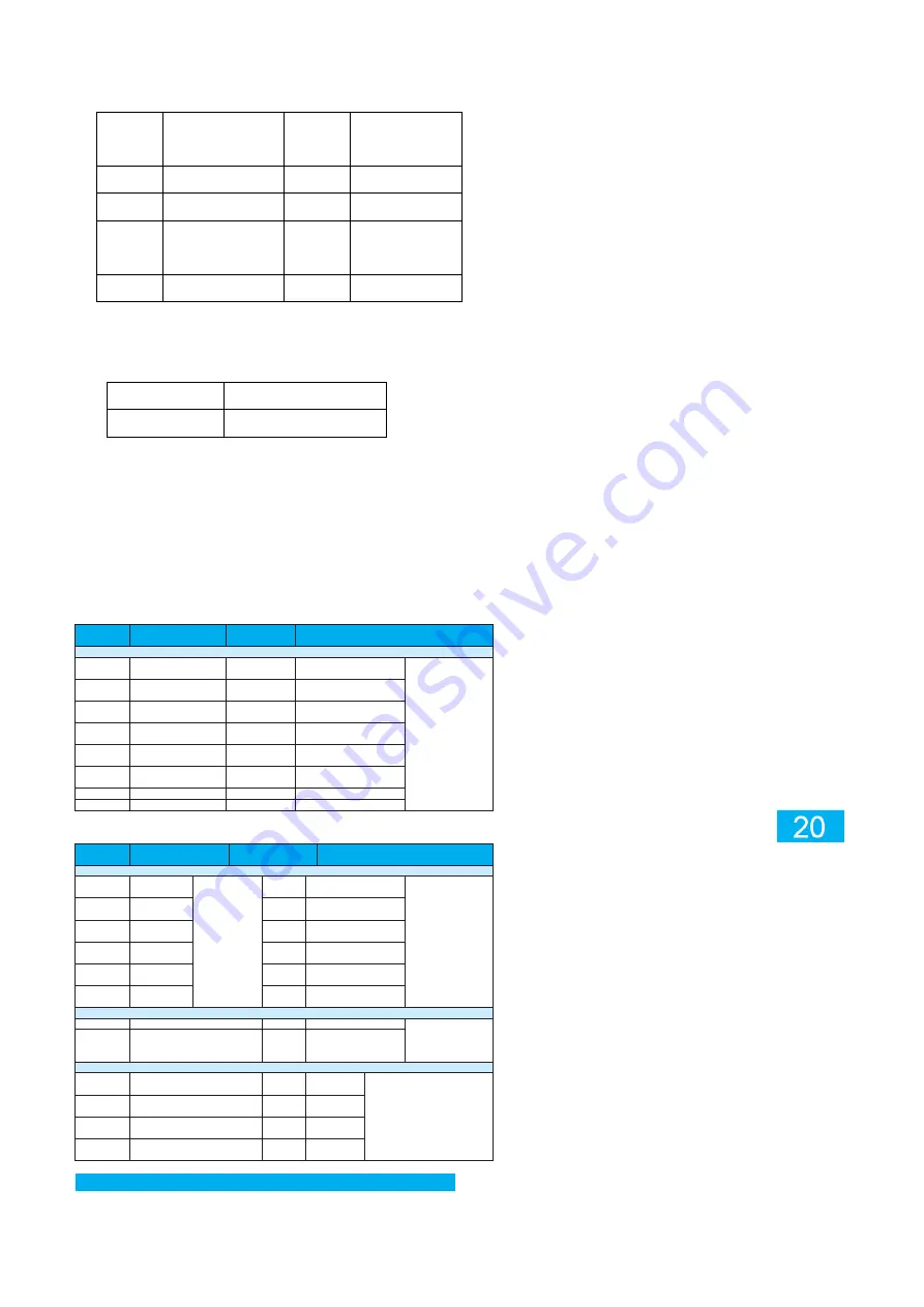
4) Analog input/output function 
6-channel  PT100  input,  1-channel  analog  voltage  input,  1-channel  analog  current  input,  4-channel 
analog voltage output are supported. Special components involved include: 

component 

Description of M 

component


D component


Description of D component


Input filtration coefficient


M8390 

Reserved 

D8390 

Temperature  sensor  1 
input 

Input filter coefficient 
Setting range: 1~64 
Default value: 8 
Clear  PLC  program 
or data component to 
reset  to  the  default 
values 

M8391 

Reserved 

D8391 

Temperature  sensor  2 
input 

M8392 

Reserved 

D8392 

Temperature  sensor  3 
input 

M8393 

Reserved 

D8393 

Temperature  sensor  4 
input 

M8394 

Reserved 

D8394 

Temperature  sensor  5 
input 

M8395 

Reserved 

D8395 

Temperature  sensor  6 
input 

M8396 

Reserved 

D8396 

Voltage/current input 

M8397 

Reserved 

D8397 

Voltage/current input 


component


Description of M 

component


D component


Description of D component


Temperature sensor 100 Thermal resistance temperature


M8400


Temperature 
sensor 1 input


Disconnection 
symbol 

of 

temperature 
sensor input 


D8400


Temperature sensor 1 
input


Temperature sensor 
input temperature 
-400~1050: 
-40.0~105.0


disconnection value: 
-32768


M8401


Temperature 
sensor 2 input


D8401


Temperature sensor 2 
input


M8402


Temperature 
sensor 3 input


D8402


Temperature sensor 3 
input


M8403


Temperature 
sensor 4 input


D8403


Temperature sensor 4 
input


M8404


Temperature 
sensor 5 input


D8404


Temperature sensor 5 
input


M8405


Temperature 
sensor 6 input


D8405


Temperature sensor 6 
input


Analog input


M8406


Reserved


D8406


Voltage/current input 1


Voltage: 0~20000: 
0~10V 
Current: 0~10000: 
0~20mA


M8407


Reserved


D8407


Voltage/current input 2


Analog output


M8410


Reserved


D8410


Voltage 1 
output


0~10000: 0~10V


M8411


Reserved


D8411


Voltage 2 
output


M8412


Reserved


D8412


Voltage 3 
output


M8413


Reserved


D8413


Voltage 4 
output


Annex C Troubleshooting and parameters of inverters 

Summary of Contents for CV800 Series

Page 1: ...n should be conducive to ventilation and heat dissipation so as to ensure the heat dissipation effect and avoid the overheat caused by the sun exposure Use the specified port when the driver is instal...

Page 2: ...ximum frequency 0 025 Control mode SVC open loop vector control synchronous motor V F control asynchronous motor Acceleration and deceleration curve Linear or S curve acceleration and deceleration mod...

Page 3: ...mpt content Parameter program modification copying and download Fast replication of parameters and program downloads Protection Protection function Overcurrent protection overvoltage protection underv...

Page 4: ...s breathable and waterproof Inverter input wiring plugPositive and negative high voltage input Inverter output wiring plug Motor UVW output Keyboard window Fig 2 Opened keyboard cover of the driver Te...

Page 5: ...component D8406 11 AD2 Analog input 2 Correspond to soft component D8407 19 AGND Analog common ground 8 CANH CAN communication Fixed 250K baud rate 15 CANL CAN communication 20 485A Channel 1 485 Opti...

Page 6: ...SS0 X input common terminal Common terminals X00 to X04 16 X05 Set No 5 X input Correspond to soft component X05 28 X06 Set No 6 X input Correspond to soft component X06 13 X07 Set No 7 X input Corre...

Page 7: ...ort Recommended cables and lugs Table 2 1 Recommended cables and lugs at DC DC side Type Name Positive output wire 2 sets Negative output wire Lug Wiring terminal M6 OT terminal M6 OT terminal Recomme...

Page 8: ...itioning in order to view status modify parameters and copy or download programs of CV800 equipment in the driving cab it is recommended to use external SOP 20 810 keyboard for commissioning It is rec...

Page 9: ...efault F0 03 Select frequency source 0 digital setting F0 08 not saved after power failure 1 digital setting F0 08 saved after power failure 9 communication setting CAB by default other options of the...

Page 10: ...tioning control panel When 23PIN aviation plug is connected to 24V the keyboard may search CV800 DCDC equipment and connected to 24V and 540VDC CV800 INV equipment may be searched When disconnect 540V...

Page 11: ...and PLC after the three devices are searched See Appendix A for information on operation Rooting is risky please keep keyboard on line during the whole copying process If power failure occurs the mach...

Page 12: ...enu Authority management Keyboard login input login password 37421 After keyboard login enter the keyboard upgrade menu i e Menu System operation Keyboard upgrade as shown in the figure below HEV BUS...

Page 13: ...he copying Fig 15 Waiting interface during upgrade Import keyboard configuration file 1 Connect the keyboard to the computer via the UBS port to see following contents on the computer Please select a...

Page 14: ...ge 15VDC Input connection mode Aviation plug pluggable OFF voltage 5VDC Input type Digital input Port filtering time 10ms Input mode Source SINK type Input impedance 4 3K Input voltage class 24VDC max...

Page 15: ...acitors and other capacitive loads may be present under the load of electronic circuits such as inverters 4 Transistor output specification Table B 5 Basic output specification of transistor Item Spec...

Page 16: ...thermal resistance input of Channel 3 PT3 Input Negative NTC thermal resistance input of Channel 3 PT4 Input Positive NTC thermal resistance input of Channel 4 PT4 Input Negative NTC thermal resistanc...

Page 17: ...latest version as background programming software of the product The software will be used for application programming and download monitoring For engineering PLC type select H1U XP The maximum progr...

Page 18: ...please refer to COM1 of general version PLC CAN communication function Controller CAN communication supports free protocol conforming to CAN2 0 protocol specification CAN communication baud rate fixed...

Page 19: ...ut 4 channel analog voltage output are supported Special components involved include M component Description of M component D component Description of D component Input filtration coefficient M8390 Re...

Page 20: ...grounded or short circuited Eliminate peripheral faults detect whether the motor is short circuited or the circuit is open The control mode is FVC or SVC without performing parameter tuning Set and tu...

Page 21: ...ted within the range from 30 to 50 In the deceleration process an external force has driven the motor to run Remove the external force or install brake resistor the maximum frequency F3 26 increase fo...

Page 22: ...ral faults Three phases of input voltage are unbalanced during motor running Check whether the motor three phase winding is normal and complete troubleshooting Driver board or IGBT module faulted Seek...

Page 23: ...reasonable range If such warning is reported the inverter will calculate the mutual inductance and no load current based on known motor parameters and the values might be different from the optimal va...

Page 24: ...frequency source X options 0 F0 05 Options of auxiliary frequency source Y range when superimposed 0 relative to the maximum frequency 1 relative to frequency source X 0 F0 06 Auxiliary frequency sour...

Page 25: ...ted current 0 01A 655 35A Determine specification F1 04 Motor rated frequency 0 01Hz Max frequency F0 10 Determine specification F1 05 Motor rated speed 1rpm 65535rpm Determine specification F1 06 Asy...

Page 26: ...0 0 F2 10 Torque upper limit setting under speed control electric 0 0 200 0 150 0 F2 11 Torque upper limit source under speed control power generation 0 upper limit number setting F2 10 1 AI1 2 AI2 4...

Page 27: ...1 0 Parameter Name Setting range Default value Change F2 53 Generation power limiting enabled 0 not enabled 1 enabled 0 F2 54 Generation power limiting 0 0 200 0 Determine specification Group F3 V F...

Page 28: ...0 50 5 F3 27 Torque error compensation time constant 0 1 10 0 0 5 F3 28 Automatic frequency ascending enabled 0 not enabled 1 enabled 0 F3 29 Minimum electric torque current 10 100 50 F3 30 Maximum po...

Page 29: ...cimal places 3 3 decimal places 1 F7 13 Accumulated power on time 0h 65535h F7 14 Accumulated power consumption 0 kilowatt hour 65535 kilowatt hour F7 15 Performance temporary version number 0 65535 F...

Page 30: ...rd latest fault occurs F9 22 Driver state when the third latest fault occurs F9 23 Power on time before occurrence of the third latest fault F9 24 Running time when the third latest fault occurs Param...

Page 31: ...ion action options 4 Units place running time expired E26 ten s place user defined fault 1 E27 hundred s place user defined fault 2 E28 thousand s place Power on time expires E29 ten thousand s place...

Page 32: ...3 100 0 100 0 0 0 FC 04 Multiple stage instruction 4 100 0 100 0 0 0 FC 05 Multiple stage instruction 5 100 0 100 0 0 0 FC 06 Multiple stage instruction 6 100 0 100 0 0 0 FC 07 Multiple stage instruct...

Page 33: ...6 J1939 message format modification and check 0 65535 0 Fd 47 ID of messeage 1 received high 16 bit 0 0x1FFF 0x1400 Fd 48 ID of messeage 1 received low 16 bit 0 0xFFFF 0x9183 Fd 49 Sending cycle 1 1 6...

Page 34: ...ing cap frequency 0 00Hz Max frequency F0 10 12 00Hz A5 01 PWM modulation mode 0 asynchronous modulation 1 synchronous modulation 0 A5 02 Dead zone compensation mode options 0 no compensation 1 compen...

Page 35: ...tor mixed mode field weakening 3 no field weakening 1 A9 21 Synchronous motor field weakening gain 0 50 5 A9 22 Synchronous motor output voltage upper margin 0 50 5 A9 23 Max generation adjustment gai...

Page 36: ...fan runs properly Input undervoltage Input voltage is lower than 250V Input terminal not powered Check the input voltage Check if the input terminal is powered Input overvoltage Input voltage is highe...

Page 37: ...5 0 F3 01 Select the number of failures to display 0 65535 0 F3 02 Fault code 1 input overvoltage 2 input undervoltage 3 Module 1 output overvoltage 4 Module 1 output undervoltage 5 Module overheated...

Reviews: