Innovative Neurotronics The WalkAide System Clinical Manual Download Page 12

20

21

Note:  

If the computer and the WalkLink were previously connected: 

 Turn on the 

WalkLink and open the WalkAnalyst software program.  The blue light on the front of the 
WalkLink should begin to blink.  The WalkAide can be attached to the WalkLink at any 
time.  The blue light in the upper left hand corner of the WalkAnalyst screen will indicate a 
solid connection to the WalkLink, and the green light will indicate a solid connection to the 
WalkAide.

5.0  Fitting Process

5.1  Pre-screening with the Peripheral Nerve Stimulator

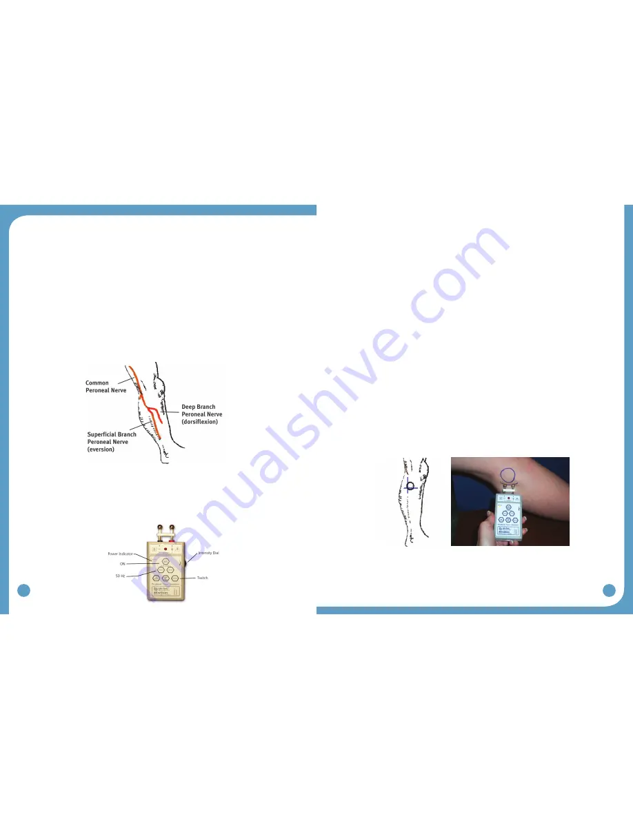
There are two primary purposes of the peripheral nerve stimulator testing procedure.  The 

first is to determine the viability of the common peroneal nerve and the degree of innervation 
of the peroneus longus (superficial branch) and tibialis anterior (deep branch) muscles.  

The second purpose is to identify initial placement of the posterior electrode to produce a 

‘balanced’ dorsiflexion and eversion movement of the foot/ankle.  (Figure 23)

Prepare the peripheral nerve stimulator by pressing:  (1) ON, (2) 50 Hz and (3) Twitch; then 
(4) set the intensity dial in between 0 and 1.  The orange power indicator light will be seen 
to indicate that the peripheral nerve stimulator is on.  (Extra 9V batteries should always be 
available)  The red light on the peripheral nerve stimulator will flash when a circuit between 
the stimulator, the nerve and the muscle is completed. (Figure 24)

1. Always prepare the user for the testing procedure by providing a thorough explanation of 

the process and always ask for continuous feedback during the procedure.  

2. The user should be comfortably seated in a chair with the affected leg resting on a low 

stool.  The leg should be relatively extended, with just slight knee flexion to simulate the 

position of the leg at terminal stance during walking, when the stimulation will be initiated.  
The heel should be somewhat supported, with the foot close to a neutral alignment. 

3. Clean the skin in the area around the head of the fibula with soap and water and wipe 

dry.  Failure to adequately prepare the skin may cause improper contact and provide less 
than ideal stimulation

4. Identify (and mark) the head of the fibula.  The common peroneal nerve runs posterior 

and distal to the head of the fibula.  (Figure 23)

  The superficial branch innervates the peroneus longus to produce eversion.

  The deep branch innervates the tibialis anterior to produce dorsiflexion (and inversion in 

a non-weightbearing condition).

5. Wet the area around the head of the fibula generously with water.  Place one hand on 

the lower leg in a position to be able to feel the contraction of both the peroneus longus 
and tibialis anterior muscles.

6. Identify the intersection of a line dropped vertically behind the head of the fibular and 

horizontally below the head of the fibula.  This is a good starting point to test for viability 
of the common peroneal nerve.  (Figure 25)

7. Position the peripheral nerve stimulator against the leg so that the black-based silver 

node is posterior and the red-based silver node is anterior.  Press the peripheral nerve 

stimulator firmly into the leg, keep the stimulator perpendicular to the leg.  Gradually 

turn up the intensity dial on the peripheral nerve stimulator until muscle contraction 
is evidenced.  Most often, this will be contraction of the peroneus longus when the 

superficial branch of the common peroneal nerve is stimulated. (Figure 25)

8. Slide or shift the peripheral nerve stimulator slightly anteriorly to find the deep branch of 

the common peroneal nerve and to produce a contraction of the tibialis anterior muscle.  
Watch and feel for any slight twitch of the tibialis anterior muscle.  Once the twitch is 
discovered, stop sliding the peripheral nerve stimulator and start increasing the intensity 

level until a more functional dorsiflexion movement is produced. 

Figure 23: Superficial and deep branches of the 

common peroneal nerve

Figure 25: Initial placement of the peripheral nerve stimulator

Figure 24

Summary of Contents for The WalkAide System

Page 1: ...physician LM06 R6 2013 Innovative Neurotronics All rights reserved All trademarks and registered trademarks are the property of their respective holders No part of this manual may be reproduced in an...

Page 2: ...9 4 1 Configuring initial set up process Pairing 19 5 0 Fitting Process 20 5 1 Pre screening with the Peripheral Nerve Stimulator 20 5 2 Electrode Placements and System Preparations 22 5 3 Fitting a N...

Page 3: ...ions Do not use on persons with implanted demand type cardiac pacemakers or defibrillators Do not place the electrodes in the carotid sinus region throat Laryngeal or pharyngeal spasms may occur when...

Page 4: ...to operate the equipment 1 5 Precautions Heart Disease Use caution in applying electrical stimulation to persons suspected of having heart disease More clinical data is needed to show that such person...

Page 5: ...Glossary AutosetWalkAide Parameters This calculation process adjusts the threshold settings to more closely match the individual data collected Audible Beep Optional Biofeedback Feature Audible signal...

Page 6: ...d Stims Per Day information since log was last cleared Restore Original Reverses Autoset Optimize functions and manual adjustments returning thresholds and control times to original values Save and An...

Page 7: ...video One free USB port for the Bluetooth Adapter Windows XP with SP2 or Windows 7 A peripheral nerve stimulator can be purchased separately The peripheral nerve stimulator uses a 9 volt battery to op...

Page 8: ...mode A non audible alarm with only a red blinking light indicates hibernation mode Establish a Bluetooth connection with WalkAnalyst to automatically clear hibernation mode If the hibernation mode do...

Page 9: ...Washing Instructions To wash the WalkAide Cuff fabric liner first remove the electrodes and then remove the liner from the cuff Do NOT remove the Black and Red Electrode Locators Make sure to Hand Wa...

Page 10: ...click on Setup exe and choose Run as Administrator Follow the set up instructions that will appear 4 The WalkAnalyst program will be installed in the Program Files Innovative Neurotronics directory un...

Page 11: ...to the WalkLink This is called the pairing process Following the guidelines below to accomplish this process Plug in your USB Bluetooth adapter with the computer powered ON Start the WalkAnalyst appl...

Page 12: ...ot close to a neutral alignment 3 Clean the skin in the area around the head of the fibula with soap and water and wipe dry Failure to adequately prepare the skin may cause improper contact and provid...

Page 13: ...de lead cable Make sure the BLACK lead negative is connected to the BACK electrode and the RED lead positive is connected to the FRONT electrode Figure 26 5 Turn the WalkAide ON by turning the blue In...

Page 14: ...nt Profile Add basic information patient ID location primary diagnosis etc and save the patient file Select Program During the initial fitting you have the following programming options Rapid Program...

Page 15: ...rrow Upon releasing the mouse the WalkAide settings are calculated and an optimization error is displayed An optimization error of less than 20 is recommended Press the Next button to program the Walk...

Page 16: ...e Log to set the internal date time stamp and start a new 69 day tracking sequence For an existing user Select Retrieve Usage Log to download the most recent walking activity data This Usage Log will...

Page 17: ...the Data Data processing involves following the sequence of icons from left to right displayed above the Tilt data graph Zoom Autoset and Optimize are the first three steps involved in processing the...

Page 18: ...cise settings Figure 41 Usage Logs Select Usage Logs tab to view and or clear usage data Figure 42 Preferred Setting You can use the checkbox Set as Preferred Setting to tag a setting as preferred set...

Page 19: ...ual Users should proceed through the daily wearing schedule and increase wearing time only if no skin irritation and or muscle soreness is present Figure 55 ON Time OFF Time Days 1 3 15 60 minutes 30...

Page 20: ...performance improvement and justify medical necessity of WalkAide Evaluation options Collect Walking Data No Device When collecting walking data with no assisted device attach the WalkAide on a cuff...

Page 21: ...de is to be stored for an extended period of time and not used remove the battery from the battery compartment When the alkaline batteries become depleted please dispose of properly in accordance with...

Page 22: ...of the leg The stimulation is optimized if it enters at the motor nerve and exits after traveling in the direction of the muscle Electrode position varies with each patient Conductivity is enhanced b...

Page 23: ...poorly timed on and off cycles that may occur with abnormal tibial motion during swing usually from ataxia Adjustment to the Min Time also addresses periods of faster walking or faster steps when the...

Page 24: ...e testing to prevent possible overstimulation of the user Recommended for pediatric or more sensitive patients a low Pulse Width may provide a less forceful stimulation and allow for a softer contract...

Page 25: ...ur methods to re optimize the user s walking program These are outlined below with clinical descriptors of when each method may be most indicated Option 1 Rapid Adjustment Adjust stimulation parameter...

Page 26: ...trial listed below Save WalkAide Settings and make any clinical comments relevant to this walking program Click on 4 Verify WalkAide Settings and change the Stimulation Mode to Hand Send Parameters to...

Page 27: ...nutes of non use Turn the WalkLink off for a few seconds and then turn it on again Click on the Bluetooth icon in the upper right corner of the screen and Search for Previously Connected WalkLinks Che...

Page 28: ...f another Bluetooth driver software is causing the conflict you may need help from your IT support team Call the Innovative Neurotronics technical support team if you have trouble resolving this probl...

Page 29: ...Reference Part Numbers 20 1000 WalkAide Patient Kit 21 1000 WalkAide Patient Kit Japan 20 1000 WalkAide Patient Kit Reprocessed 20 0100 WalkAide 21 0100 WalkAide Japan 20 0100R WalkAide Reprocessed 2...

Reviews: