INMES Industrial Ltda – IM-30 MM
14
Second:
The operator may press down on the yellow lock disc on the front of the machine to disengage it,
then rotate the saw table until it reaches the position desired, then engage the lock again by releasing
the disk, taking care to have the position properly aligned, so as not to damage the lock pin.
It is possible to obtain the manual adjustment, as before press down on the yellow disk to
disengage the lock, rotate the saw to the angle desired, and then release the yellow disk, then tighten the
screw on top of the fence with your 5mm Allen wrench, which locks the rotating table in place.
Depending on type of frame to be made, follow the table below:
Sides Angle
04 45°
06 30°
08 22,50°
12 15°
18 10°
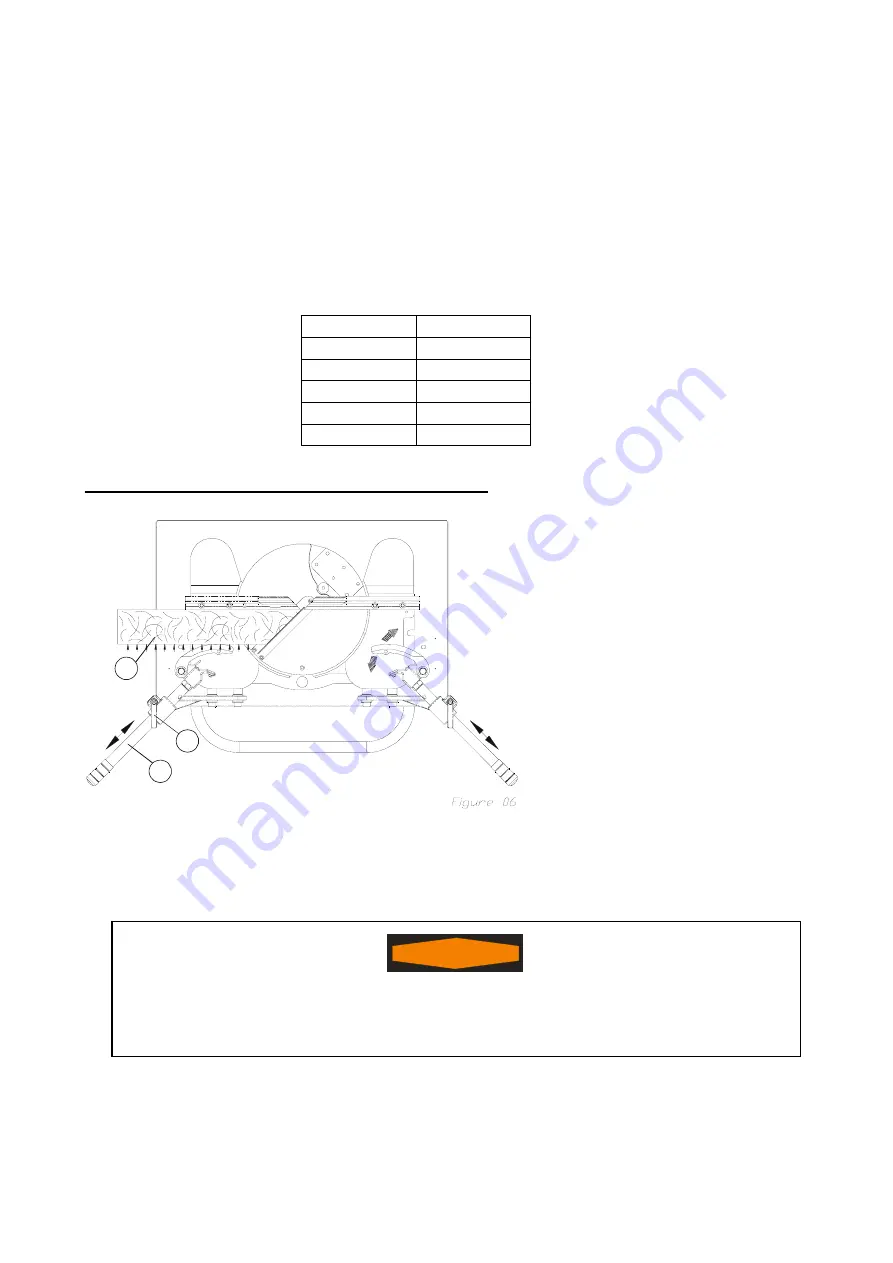
8.3 – Operating mechanical clamping system
1. Choose the profile you wish to cut (01);
2. Release the handle (02);
3. Step on the foot pedal (05) all the way
down, and keep it pressed;
4. Adjust the clamping system (03) in the
way of the arrow “A” in order to fit the
profile;
5. Place the profile between the fence
and the clamping;
6. Tight the handle (02);
7. Release the foot pedal (05);
8. Make sure to obtain a space of about
3/8” (10mm) between the clamping and
the profile before releasing the foot
pedal;
9. Observe that when stepping on the foot pedal (05) the clamping (04) moves in the way of arrow
“B” and “C”;
10. The clamping clamps the profiles in the way of arrow “D”
WARNING
!
Before cutting, observe the clamping (04) fig (06); if it’s clamping the profile in the
correct way, otherwise it’s possibly to release during cutting, damaging the machine, or
even hurting the operator.
01
02
03
A
A
B
C


