background image


9" (230mm) SLUGGER METAL CUTTING SAW


INSTRUCTION MANUAL 


Double Insulation

                                        Slugger order number: 69908120001 

Original instruction 


Summary of Contents for 60250

Page 1: ...9 230mm SLUGGER METAL CUTTING SAW INSTRUCTION MANUAL Double Insulation Slugger order number 69908120001 Original instruction ...

Page 2: ...ety warnings and all instructions Failure to follow the warnings and instructions may result in electric shock fire and or serious injury ADDITIONAL SAFETY RULES OF METAL CUTTING SAW CAREFULLY READ THE FOLLOWING SAFETY WARNINGS PRIOR TO CONNECTING THE METAL CUTTING SAW TO POWER 1 Must keep the safety device in the fixed position and work according to the order Never wedging or binding the safety d...

Page 3: ...nts Power Supply and Motor Specifications The AC motor used in this saw is a universal Nonreversible type having the following specifications Model No 60250 Maximum Developed H P 2 4 Voltage 120 Amperes 15 Hertz Cycles 60 Phase Single RPM 2300 Rotation of Shaft Counter clockwise Power Connections A separate electrical circuit should be used for your tools This circuit should not be less 12 wire an...

Page 4: ...s could void warranty Check regularly that the blade is flat sharp and free of any defects or damage Ensure the saw is disconnected from Power 1 Push the lower guard lever A Refer to Fig 1 2 Open the plate to the maximum B Refer to Fig 2 3 Use the open end wrench D to hold the flange use 6mm HEX wrench C to loosen the arbor screw in counterclockwise direction Refer to Fig 3 4 Remove the HEX wrench...

Page 5: ...e saw Refer to Fig 6 1 Beginning at a corner line up the sight line with your cutting line Tilt the saw forward firmly fixing the front of the shoe on the work piece The blade should be just above cutting line but not touching it Raise the B lower guard using the lower guard lever A 2 Pull the trigger and allow the motor to reach full speed before beginning cut Using the front of the shoe as a hin...

Page 6: ...age A to turn o according at the not angles are A Fig 8 Usag wing nut B Refer to F the power LAS on the lase to the ang tch B if t without ref B 6 ge for b B then ch Fig 7 plug SER r B push gle plate fo the bevel i ference B Fig 7 A bevel hange the b h again to t or guiding t indicator a C C bevel plate turn off Re the cut Ex at 45 then C C e angle from efer to Fig ample the n laser is a Fig 9 B A...

Page 7: ...ighten or loosen the A for adjusting the laser indication direction Adjusting tooling M2 HEX wrench A as Fig 11 2 Adjusting the laser indication direction to be same line as cutting line Adjusting tooling parallel screw driver A Fig 12 3 Adjust the laser line B on the notch C then set up the bevel scale at the 0 position Fig 13 How to use LED light LED is used when the condition is dark and user c...

Page 8: ...tate it slightly as required Warning 1 Make sure the motor is stopped before changing the cutting height 2 Cutting with a loose Lock Lever invites injury OPERATION Operation of Switch Press the stop button A first and pull the trigger B at the same time to start rotating To stop rotating release trigger Fig 17 Operation Please use right hand A to hold the rear handle and left hand B to hold the to...

Page 9: ... the saw from its power source Wait about three minutes for the motor to cool down Push in on the reset button and turn the switch to the on position Refer to Fig 19 THE GUIDE RULER The guide ruler can be used to cut a straight sawing line along the workpiece and can be affixed at the front of base with the wing nut The guide ruler C can be used on the right side of the blade only shown in Fig 20 ...

Page 10: ... way through cut to ensure proper blade operation and to obtain smoother cutting Beware Beware of the kickback at the instant the running blade touches the workpiece CHIP REMOVAL GLASS WINDOW The chips can be observed through a glass window When the chip shield area is half full remove the cover by loosening the two bolts and empty the contents Make sure the chips have been removed completely Way ...

Page 11: ...ce brushes Carbon brushes should be clean and slide freely in holder Carbon brushes should be replaced in pairs Use a flat blade screwdriver to remove the brush cap A take out the worn carbon brush B insert new carbon brush and secure the brush holder cap Refer to Fig 25 MAINTENANCE AND SERVICING Disconnect tool from power supply before carrying out any servicing and maintenance Keep the machine c...

Page 12: ...tion Contact repair center Possible short circuit Contact repair center Blade out of balance Replace blade Heavy sparking inside motor housing Brush not moving freely Disconnect power remove brushes and clean or replace Possible short circuit dirty commutator Contact repair center SPECIFICATONS Rated voltage 110 120V 50 60Hz 220 240V 50 60Hz Rated input 1800W No load speed 2300min 1 RPM Arbor 15 9...

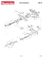
Page 13: ...PARTS 13 S DIAG GRAM M ...

Page 14: ...ING 18 69908120019 EXTL RETAINING RING 19 69908120020 WASHER 20 69908120021 GUARD LOWER 21 69908120008 BOLT M4X0 7 10MM PAN HEAD PHILLIPS 22 69908120007 LOCK WASHER 23 69908120024 INNER BLADE GUARD 24 69908120025 SCREW SELF TAPPING CLAMP 25 69908120026 SCREW 26 69908120027 SPRING 27 69908120028 BOLT FLAT HD 28 69908120025 SCREW SELF TAPPING CLAMP 29 69908120025 SCREW SELF TAPPING CLAMP 30 69908120...

Page 15: ...LT M4X8MM PAN HEAD PHILLIPS 64 69908120069 OIL SEAL 65 69908120070 OIL SEAL BOX 66 69908120071 SCREW M6X1MM 67 69908120072 WASHER D5XD13X2T 68 69908120073 LED LIGHT CAP 69 69908120074 LED COVER 70 69908120075 LED LIGHT 71 69908120076 LED SEAT 72 69908120077 SCREW M3X1 06 8MM PAN HEAD PHILLIPS PLASTITE 73 69908120078 PAN HEAD SCREW 74 69908120079 NYLON SCREW CAPS 75 69908120080 O TYPE RING 76 69908...

Page 16: ...9 WING SCREW 107 69908120111 SPRING SHAFT LOCK BUTTON 108 69908120112 SCREW 109 69908120113 BASE PLATE 110 69908120114 LOCK LEVER 111 69908120115 FLAT WASHER 112 69908120116 BEVEL LOCKING PLATE 113 69908120117 MITER INDICATOR 114 69908120118 CROSS RECESSED TRUSS HEAD SCREW 115 69908120119 SET SCREW 116 69908120120 NUT LOCKING 117 69908120121 CARRIAGE SCREW 118 69908120122 RACKET 118 1 69908120123 ...

Page 17: ... DC TRANSFORMER MODULES 144 69908120148 TRANSFORMER 145 69908120149 EXTRUDED TUBING 146 69908120150 WIRING CONNECTOR 147 69908120151 WIRING CONNECTOR 148 69908120152 WIRING CONNECTOR 149 69908120153 CORD CLAMP 150 69908120025 SCREW SELF TAPPING CLAMP 151 69908120155 SET SCREW 152 69908120156 SELF TAPPING SCREW 153 69908120157 SELF TAPPING SCREW 154 69908120158 SET SCREW 161 69908120160 WRENCH 162 ...

Page 18: ...To Tel 412 922 ns carefully s when us from the pa g from the ct eye cont tools togeth t touch the Cautio ools Inc 10 8886 Toll F 18 y before sta ing the ma ath of the s socket bef tact with lig her with ho e metal pa on Laser ra 030 Alcon Str ree 1 800 4 arting the m achine saw blade fore carryin ght source ousehold w rts to avoid adiation do reet Pittsbur 41 9878 ww machine ng out any waste mate ...

Page 19: ......

Page 20: ......

Reviews: