background image

131

Chapter 7 Share

The Share window displays the currently available Folder Groups that are ready to provide 

shared storage over the network. 

7.1. Share - Adding Shares 

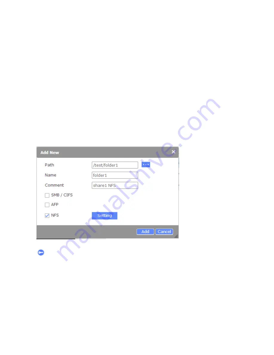
Once you create a Folder Group within a volume, you can create a share in the Share 

window by clicking the 

Add

 button. 

An Add New window will appear:

1. Click on the Find button on the right to select a directory under the storage volume (those 

that you created previously.) Select a Folder Group.

2. The 

Name

 of the Folder Group will appear automatically.

3. Add comments to the share, such as share1 for NFS. 

4. Select a file system to which you want this share to be accessed. 

5. Click the 

Add

 button to complete the process.  

To examine the account who can access the share, you can click on the Permission button  

 on the right to visit the Account > Permission window. 

Summary of Contents for nastorage 12600 series

Page 1: ...1 NAStorage 4600 12600 12620 Series Tower 1U 2U Rack mount User Manual Rev 1 1 ...

Page 2: ...rence to radio communications Operation of this equipment in a residential area is likely to cause harmful interference in which case the user will be required to correct the interference at his own expense CE Notice This device complies with the EMC directive of the European Community and meets or exceeds the following technical standard EN 55022 Limits and Methods of Measurement of Radio interfe...

Page 3: ... off and unplugged and all connections must be removed Safety Notices The computer may provided with CD drives comply with appropriate safety standards including IEC 60825 Caution This unit is provided real time clock circuit There is a danger of explosion if battery is incorrectly replaced Replace only with 3 Volt Lithium cell CR2032 or equivalent type Discard used batteries according to the manu...

Page 4: ... 12620U 23 2 4 Installing Disk Drives 4600U 12600U and 12620U 26 2 5 Optional PCI E adaptor installation Only for 12600U 12620U 27 2 6 Connecting Expansion Enclosures for 12600U 12620U 28 2 7 Starting the System 30 2 8 Shutting Down the System 30 2 9 Drive Tray LED Definitions 31 2 10 Install the NASFinder Utility 32 2 11 Using the Top Screen Tools 36 2 12 Configuring IP Address Using the LCD Keyp...

Page 5: ... Account Windows AD 100 5 3 Account UNIX NIS 104 5 4 Account Permission 105 5 5 Account Permission ACLs 107 5 6 Account Permission Effective 109 Chapter 6 Service 111 6 1 Service Status 111 6 2 Service Windows 112 6 3 Service Apple 113 6 4 Service Unix NFS 114 6 5 Service FTP 115 6 6 Service iSCSI Targets 117 6 7 Service Rsync 127 6 7 Service Replication 128 Chapter 7 Share 131 7 1 Share Adding Sh...

Page 6: ...les 153 11 3 Status Connections 153 11 4 Status Task Progress 154 11 5 Status Loading 155 Appendix A More about RAID Storage 156 The Key Differences between the 4600U T and the 12600 Models The 4600U T series does not support the Dedup Copy and Sync disable functions The Compression function is supported The 12600U series supports Dedup Compression and yet the Copy and Sync functions can not be di...

Page 7: ...es a local or remote storage server 1 2 Conventions Terminology The term NAS server means all the models of the network attached storage servers unless the specific model is mentioned Typographic Conventions Conventions Meaning Italic Variable name which should be replaced by user defined text in context Bold Menu item or functions Underline Cross reference Symbols and Statements in this Document ...

Page 8: ...cover is opened it s a secure design to defend invader from powering off the system C Power LED blue D System Read Write LED Orange E Front cover bezel lock F USB port For backup data G USB port For backup data H LCM control buttons Left Enter Right I LCM for system status display and IP address settings J System status LED System Normal Green System Warning or Faults occurred Red 4600T Front View...

Page 9: ...ust outlet Power Socket 4600T Rear View HDMI 4600T LED Definitions LED1 Status error LED2 Disk access Definition Constant Green OFF No access to H D D Constant Green Blinking Green Access to H D D LAN2 LAN1 UID button LED1 LED2 USB combo 2 0 ...

Page 10: ...he system on or off pressed for one second Reset button Resets the system LAN1 LED Network transaction status LAN2 LED Network transaction status UID LED Indicates the system is currently being identified Pressing the Server Identify button will also light up the LED System Status LED Displays the system operating statuses UID button Lights the UID LED system notification Items are listed accordin...

Page 11: ...C ports SATA expansion ports LED Serial ports 12600 Series Front View Power button USB ports Reset button UID button Status LEDs ID switch 12620U Rear View LED ID switch LAN or WAN VGA Power supplies IPMI USB ports FC ports SATA expansion port Serial ports 10GbE ports ...

Page 12: ...ystem LED Definitions Front Panel Indicator error Color Description System Status BMC ON Amber Event in BMC marked with has happened System Status Blinking Amber Voltage sensor critical System Status ON Green System working normally System Status Blinking Green Fan Temp sensor critical or chassis intrusion alert HDD Blinking Green Internal SATA DOM activities BMC No function UID Blinking Blue The ...

Page 13: ...up the basic configuration through the Admin Home page or provided software tool NASFinder is also outlined in this chapter 2 1 Installing the NAStorage controller mobile rack Package Contents NAS server controller package Two RJ 45 ports and one serial connector Two Ethernet cables NAS server Quick Installation guide NAS server utilities CD 4600U rack mount model package One slide rail package fo...

Page 14: ... you use hard drives of the same model featuring the same capacity and rotation speed even running the same version of firmware 2 1 Hardware Installation 4600T SATA hard disk s are user supplied The NAS server can readily accommodate most of the off the shelf SATA hard drives For the latest compatibility list please check on our website 1 Use the included bezel key to open the front panel 2 Use th...

Page 15: ...ecure the hard drive by fastening 4 screws from both sides 5 Install drive tray by pushing it into drive bay when it is almost fully inserted close the bezel The bezel will secure the back end connection to the backplane 1 2 HDD Bezel Lever Avoid touching the hard drive s circuit board or connector pins Doing so can damage the hard drive by electro static discharge IMPORTANT ...

Page 16: ...16 6 Use the bezel key to lock the drive tray Repeat the above process to install more disk drives Bezel Lock ...

Page 17: ...cription 1 Connect LAN ports to a local area network 2 Power cord to the power supply 110 240V 3 5A 47 63Hz 3 15 pin VGA and HDMI to monitor 4 eSATA port for backup to external storage devices 5 USB ports to USB devices e g thumb disks for backup keyboard and mouse ...

Page 18: ...ys from the server 2 Secure the left and right side slide rails to the rack posts Secure the rails to rack posts using 8 of the included pan head screws Use screws P N 2A5816C00 600 G for square hole racks Use screws P N 2A5816D00 600 G for round hole racks The mounting holes and installation methods are identical for the rack mount models 12600U and the 12620U ...

Page 19: ...19 3 Remove the inner rail from the slide rail assembly Pull out the inner rail and then pull the release tab to remove it from the rail assembly ...

Page 20: ...20 4 Align the inner rail with the protruding rivet head and then push the inner rail towards the front of the enclosure The inner rail should snap fit to the side of enclosure ...

Page 21: ...21 5 Secure the inner rail to the side of enclosure using 3 included flathead screws Repeat the above process to install another inner rail to the right hand side of the enclosure ...

Page 22: ...n insert the tips of the inner rails into the en trance point on each of the middle rails 6 3 Slowly move the enclosure in to engage the inner rails with the slide rail assembly 6 4 When slided half way the rail lock will engage Press the release tabs on both sides to slide the enclosure into rack cabinet ...

Page 23: ...kmount enclosure to a rack cabinet 1 Attach the inner and middle rails to the rack cabinet See previous description 2 Attach the cabling management arm to the rear of the slide rail assembly The mounting holes and installation methods are identical for the rack mount models 12600U and the 12620U 1 2 3 4 6 ...

Page 24: ...24 3 Attach the inner rails to the sides of the chassis 4 Gradually slide the chassis into rack ...

Page 25: ...25 5 Engage the tips of inner rails with that already installed on the cabinet Push the chassis into the cabinet ...

Page 26: ...Plug the power cord into the power connector on you NAS server 9 Make sure the power switch on the power supply is in on position 10 Press the power button on left of the front panel on NAS server 2 4 Installing Disk Drives 4600U 12600U and 12620U Follow the procedure to install a rack mount enclosure 1 Remove a HDD tray from the server by press the release tab 2 Secure and mount a hard disk onto ...

Page 27: ... on the riser card 5 Tighten the screw for the adaptor 6 Reinstall the riser card support bracket and make sure that the riser card is fully seated in the PCI E slot on the main board 7 Tighten the screw for the riser card support bracket 8 Close your server case and plug in your power cable 9 Turn on the NAS server 10 New PCI E adaptor is now installed Note that only the PCI E cards certified by ...

Page 28: ...o the 12600U NAS first use a small size Phillips screw to set up the enclosure IDs These IDs are necessary to address the WWN addresses for the hard disks inside the expansion enclosures Set the NAS server ID to 0 and the IDs on the JBOD enclosures consecutively The configuration supports up to 3 JBODs ...

Page 29: ...gured Port 0 Port 1 12600U ID 0 JBOD 1 1200J ID 1 JBOD 2 1200J ID 2 JBOD 3 1200J ID 3 IMPORTANT 1 For the 12620U model there is no ID switch The chassis has a default ID 0 and there is no need to change this default ID 2 Make sure you configure the SAS SATA expansion chassis ID JBOD to numbers other than 0 ...

Page 30: ...kes approximately 5 minutes 2 8 Shutting Down the System 1 Shut down the system pressing the power button once The whole shutdown process might take seconds or minutes until data can all be safely distributed to disk drives 2 To shut down the server from the management page you can find the button on the upper right of the NASFinder screen 3 To configure automatic power on and shutdown you can sel...

Page 31: ...as already been exported unmounted and is ready for removal OFF OFF No power or HDD is absent If you lost your access to the 12600 series system try connect the D SUB 15 connector to a monitor and a mouse and a keyboard Try to access the system using the NASfinder If you still can not access the system press the Reset button for more than 10 seconds to restore the system defaults especially if the...

Page 32: ...The default administrator account and password are admin and admin 2 Install the utility by starting the NASFinder Setup exe 3 Follow the onscreen instructions to install the software Tips If you are prompted to install plug ins or allowance to execute the program when installing the software follow the prompts to accept the installation ...

Page 33: ...2 168 1 1 If your router or other network devices are using the same IP address an error message will appear NOTE If this condition occurs 1 Stop the system by pressing the Power button 2 Connect the LAN cable directly to your PC s LAN port 3 Configure your PC s IP address to 192 169 1 X to the same subnet 4 Open a browser session with the NAS server using the 192 168 1 1 address 5 Change the NAS ...

Page 34: ...ing that of Host name Domain Product name Serial number firmware rev no and so on 6 After the change to listening to a DHCP server you need to connect the cables to a network switch or router where a DHCP server is present Make sure your DHCP server is up and running and can be reached by both the network switch and the management computer ...

Page 35: ...AN Uses this button to remotely power up a NAS server via network connections Remove Removes a detected NAS server from the managed queue File Opens up a Folder Group in a network share If there are multiple NAS servers in your network you can select the checkboxes in front of them and enlist them into the management queue NOTE Admin is a built in administrator account It is like the root account ...

Page 36: ...d for 5 minutes the server will require you to log in again the next time you access the web console to prevent unauthorized access NOTE 2 11 Using the Top Screen Tools 1 Event Click on the Event button to display the Event window which lists recent events 2 Account Click on the Account button to display the Restart Shutdown and Logout commands A confirm box will prompt for reassurance of command ...

Page 37: ...gure LAN 1 Yes No LAN 2 mask 255 255 0 0 LAN 2 gateway 192 168 2 254 LAN 2 IP 192 168 2 1 Configure LAN 2 Yes No Configure LAN 1 IP Gateway Mask Configure LAN 2 IP Gateway Mask Server Name NASD800xxx Date Time 8 21 2014 06 30 Firmware Ver V1 00 CPU Fan Speed 3994 RPM Thermal ºC 67 50 Voltage V 1 44 3 30 4 68 System will automatically display the next screen every two seconds when idle ...

Page 38: ... Right Left 2 The IP address of LAN 1 is shown Press the Enter button to configure its IP address Note that the symbol on the upper right corner indicates that the IP address can be configured using the LCD console LAN1 IP 192 168 170 171 3 Move the cursor to Yes using the left right buttons and then press the Enter key to confirm Configure LAN 1 Yes o N ...

Page 39: ...eps 4 to Steps 5 to configure the Subnet Mask and Gateway address 7 After you edit the last digit of the Gateway address press the right button Move the cursor to Save and save the setting or Edit to repeat the above process or Abort to quit the configuration process without saving 7 After you edit the last digit of the Gateway address press the right button Move the cursor to Save and save the se...

Page 40: ...ration and system log configuration pages 3 1 System General Page The General page provides access to changing the Host Name Domain system description and a Server Identify function This page displays on the first log in If you have multiple servers in a location and can not be sure where your server is use the Server Identify button to light the UID LED ...

Page 41: ...ime zone click on the empty Etc UTC entry field A pull down menu of all time zones on earth will be available from the pull down list You may then manually configure a time by clicking on the empty entry field or select the check circle of Use your computer s time When doing so your NAS server s time will be synchronized with that of the PC you use to make a web console ...

Page 42: ...ronize its time with the time server 3 2 System Overview The Overview page provides a glimpse of current CPU and memory resources network flow and Storage uses and the direct access to the working statuses of hard disk drives You can also click on the status icons on the lower left of the screen to move to the Status window to get more details of the current operation status Thermal events System ...

Page 43: ...such as IP Address subnet mask gateway MTU Speed Mode and DNS related information 3 Server Shows your current Domain Name server and default gateway 4 Servers Displays the servers present in your local and Internet networks such as the NTP server WINS server and HTTP Proxy A Proxy server is one that acts as an intermediary for requests seeks resources over the network The Proxy server ficilitates ...

Page 44: ...mbining aggregating multiple network connections in parallel to increase throughput and provides redundancy in case of single link failures Each of the LAN port can be configured into the following operation modes Stand alone no fault tolerance and no combined throughput Failover two or more LAN ports formed into fault tolerant team of physical links 1 LAN Port Setting Network teaming mode ...

Page 45: ...l finds a device on the opposite end of the link is LACP enabled frames will be sent over multiple links as if they are transmitted over a single logical link Load Balance Transmit network packets in sequential order from the first available network interface NIC slave through the last This mode provides load balancing and fault tolerance Note that corresponding configurations must also be enabled...

Page 46: ... Jumbo Frame MTU and the Wake on LAN options The Jumbo Frame refers to the maximum packet size of up to 9 000 bytes local network or to be compatible with transmission over the Internet 1 500 bytes The Wake on LAN setting available for the 4600 series only enables you to power up the server Wake On LAN allows administrators to remotely power on your NAS server to perform maintenance task with no n...

Page 47: ...page and the administration homepage To use SSL 3 0 the NAS server will generate a server certificate for authentication and data encryption By default the server certificate is issued to the NAS server designated by its IP address You can also specify to use the server s full name on the server certificate ...

Page 48: ...s web pages via SSL encrypted connection Suppose that the server IP address is 192 168 1 10 To access the NAS system s web pages with SSL connection please open https 192 168 1 10 for the user homepage or https 192 168 1 10 admin for the administration homepage If the server certificate with the server name is chosen please open https server_name instead To utilize encrypted access follow the step...

Page 49: ...49 2 On the management computer open a web browser e g IE Click on the Tools button and enter the Internet options page 3 Click Content and Certificates on the Internet Options page ...

Page 50: ...50 4 Click to open the Trusted Root Certification Authorities tab Click the Import button ...

Page 51: ...51 5 The Import Wizard page will start Click Next 6 Click Browse to locate the certificate file you download Click Next to proceed ...

Page 52: ...52 7 Select the location where you want to store the certificate and related information 8 Click Yes on the Security Warning prompt ...

Page 53: ... Now return to the NAS sever console System Maintenance Select the Enable https SSL connection checkbox and enter the default Https Port number default is 443 On leaving the page enter the administrator s login password and click the Apply button ...

Page 54: ...54 11 Also make sure the SSL option has been enabled on your browser s Internet Options 12 You can now enter https NAS server IP address to start a secure and encrypted management access ...

Page 55: ...ghly recommended to provide a secure password with the combination of alphabetic symbol and numeric characters as the administrator s password Web Management The default management access is via TCP port 80 You can assign a different HTTPS port for access through the Internet and through a firewall If a different https port has been assigned and opened on the router specify its TCP port so that ma...

Page 56: ...stem Folder Group which is required for saving system files or performing related functions System Volume If you have created more than one volume you can specify which is the default system volume This option will only appear after you configured a storage volume The information on this page is mainly for the user reference ...

Page 57: ...wnload the MIB file Community A name serves as a simple authentication The communication between the SNMP management console and the NAS server cannot be established if the community names do not match Port Default is 161 change it if necessary Location Provide location information of the SNMP agent Contact Provide name of the contact person who has the management information of the SNMP agent SNM...

Page 58: ...G SOFT MIB browser or similar SNMP utility http www mg soft si download html 3 Open the MG SOFT MIB Compiler and select the NAS server s MIB file you previously downloaded 4 Select the Ingrasys MIB module and then click Save to proceed ...

Page 59: ...59 5 Save the compiled module to a position as shown below ...

Page 60: ...60 6 Open the MIB browser 7 When the MIB browser is started click on the MIB tab Search and locate the IngraNAS MIB module from the list below ...

Page 61: ...ote SNMP agent s IP that of your NAS server and then click on the Query button 9 The SNMP Protocol Preferences window will prompt Configure the SNMP version Community settings to the same configuration on your NAS server ...

Page 62: ...62 10 When successfully connected the Ingrasys MIB location will be shown Note that currently the NAS server supports the Get command only Right click on the MIB profile entry to select the Get command ...

Page 63: ...and if SSL certification is required select the SSL option Note that TLS certification is currently not supported 2 Next enter the User Name Password and the address of a Mail Notification Receiver 3 Click on the Apply button 4 Click on the Send Test Mail button to see if you can receive a test Email from the receiver s mail address ...

Page 64: ...pull down menus will then be enabled 2 Select the day in a week or a day in a month for the reboot to take place 3 Select a Start Time and click on the Apply button You can also configure a scheduled Shutdown using the method described above You can configure the server to automatically power up by a preset schedule 1 Select the checkbox to enable the schedule The options and pull down menus will ...

Page 65: ...locate the firmware file and then click the Upgrade button to proceed NOTE 1 Your current file services will be interrupted because the upgrade process will reboot your server 2 When upgrading firmware please visit the Status Task Progress window to check if any application is still running If so please wait for the application to complete or manually end the progress to ensure that a running appl...

Page 66: ...restore system defaults All previous system configuration will be erased and returned to factory defaults The data stored on your disk volume will remain intact Note that the server IP will be restored to 192 168 1 1 and the default password will become the original admin ...

Page 67: ...tically displayed at the bottom You can click the Download button to save the backups to your PC If you should need the help of our technical support you can also download and send the configuration file to our engineers To delete a backup click the checkbox in front and then click the Delete button NOTE 1 The system will automatically back up the user configuration including account database and ...

Page 68: ... can select a previous backup using the drop down menu by selecting the date it was created 2 If you saved your backup to somewhere else e g a PC that once had a management session you can upload the backup using the External File option 3 You can then click on the Restore button A server reboot is automatically applied ...

Page 69: ...ly button 2 Get Latest Log Click the Get Latest Log button to retrieve a system log record You can then download the system log to your PC The system log file will be saved to a preserved space on your storage volume A list of previous logs will be automatically displayed at the bottom You can click the Download button to save the backups to your PC If you should need the help of our technical sup...

Page 70: ...Before using this feature it is suggested that you install a log recording tool such as the Kiwi Syslog Daemon from http www kiwisyslog com kiwi syslog daemon overview To enable remote log select the checkbox enter the IP address where the log recording software resides select the log level and then click on the Apply button ...

Page 71: ...following benefits 1 Independent operation via an out of band connection which is good for a re start and is independent regardless of whether the system is on or off 2 Ease of expansion sensor or controllers can be easily added 3 CPU is connected to BMC which means that the event log can be easily delivered This window provides a glimpse of system operation statuses The adjacent Events LAN Accoun...

Page 72: ...ess to the current conditions of all disk drives installed in your chassis The action button lights the disk activity LED of a drive tray for identifying a specific disk drive in a chassis When you need to locate a physical disk drive click on a disk entry and then click on the Position tab button to display a virtual layout of the position of the currently selected disk drive Click on the disk dr...

Page 73: ...73 The LED on the designated drive tray will light Red If you have other storage connected to the server e g a JBOD you can select a different enclosure using the Select Enclosure menu ...

Page 74: ...ted to the attributes implemented by the HDD manufacturers Although attributes are drive specific a variety of typical characteristics can be identified for example Head flying height Data throughput performance Spin up time re allocated sector count seek error rate seek time spin try recount and drive calibration retry count etc Disk Temperature Monitor Depending on the ambient temperature of you...

Page 75: ...Once it is highlighted the tab menu buttons on top will turn blue You can click on the Information tab to check on the disk drive s working status in terms of its Read Error throughput performance spin up time reallocated sector etc These information are listed in the pop up window ...

Page 76: ... Rapid test checks the electrical and mechanical performance as well as the read performance of the disk Electrical tests might include a test of buffer RAM a read write circuitry test or a test of the read write head elements Mechanical test includes seeking and servo on data tracks Scans small parts of the drive s surface area is vendor specific and there is a time limit on the test The test che...

Page 77: ...scheduled to take place in the off office hours For example you can use the Schedule tool to perform such tests on Sundays Click on the Schedule tab to start the configuration window Select the Enable checkbox and configure the time the S M A R T test will take place ...

Page 78: ... access from different users across the network Volume Logical Disks Folder Groups iSCSI targets Users H D D NOTE 1 The NAS server supports the backup using the Rsync function to USB or e SATA devices including USB thumb disk USB hard disk or hard disks attached via the e SATA interface When the external device is attached to the NAS server it is automatically mounted The user can then mount or un...

Page 79: ...a name for the volume 4 2 1 Volumes The Storage Volumes page provides configuration and maintenance for logical volumes that consist of multiple disk drives Logical volumes provide joint performance and fault tolerance in the event of single or dual disk drive failures ...

Page 80: ...n technology featured by ZFS in order to reduce the block overhead in mirroring RAID Z can prevent the RAID 5 write hole using the copy on write technology rather than overwriting data It writes to a new location and then automatically replaces the pointer to the old data It simply avoids the need for read modify and then write operations for small writes by only ever performing full stripe writes...

Page 81: ... Name Total capacity GB Used capacity Free capacity used Capacity and Health Export A logical volume can be exported for applications such as moving an entire volume meaning its member disks to a different enclosure for initializing another system or for backup and test purposes Once exported the volume becomes de activated and will not receive disk I Os Destroy A logical volume is disbanded or de...

Page 82: ...of an exported pool this command displays a summary of the volume with the name of the volume a numeric identifier as well as the device layout and current health of the device for each device or file Destroyed pools that is pools that were previously destroyed with the zpool destroy command are not listed unless other options are specified The numeric identifier is unique and can be used instead ...

Page 83: ...disk member 3 Attach a new disk member 4 Detach a disk member from a volume 5 Bring disk member online or offline 6 Add a spare disk for the volume Add Disk Add disk groups to an existing volume Note that a disk group thus added can not be removed from a volume Select the disk drive you prefer and click Add to join it to the volume ...

Page 84: ...lete the replacement process will depend on the volume size and the size of data kept in the volume Attach NOTE The Attach function only applies to RAID0 and RAID1 The Detach function only applies to RAID1 They do not apply to RAID Z1 and RAID Z2 volumes To attach new a disk drive to an existing RAID0 1 volume click on the Attach button in the Disk Groups window Select from the available disks bel...

Page 85: ...ear Click Detach to proceed Online Offline The Offline mode is mainly designed for you to perform the replacement task A disk can be changed to the Offline mode so that you can replace a faulty member disk When the faulty member is replaced system will automatically resilver the disk status The Online and Offline functions allow you to temporarily disband or re join a member disk from the storage ...

Page 86: ...s main memory ARC a replica is immediately placed at the SSD ARC Once the data needs to be read once again data can be rapidly retrieved from the SSD ARC also known as the L2 ARC Add Intent Log Disk The Intent Log index record keeps the transaction record using an added SSD disk The file system utilizes this methodology to facilitate data writes while maintains the safety of files in the event of ...

Page 87: ...xternal devices such as USB drives formatted in the Windows FAT and NTFS format These external devices can be mounted and unmounted using the onscreen functional buttons You can click on the name entry to directly access the files or folders contained within ...

Page 88: ...h other users on the network When you create a share you can assign the access permission to the share with access rights for other users as well To create a Folder Group 1 Go to Storage Folder Groups 2 Select a volume from which you want to create a Folder Group 3 If you want to create a new share under an existing Folder Group select an existing Folder Group from the Target Folder Group drop dow...

Page 89: ... series does not support Dedup and Copy functions 2 Deduplication is the process of eliminating duplicate copies of data Dedup is generally either file level block level or byte level Chunks of data files blocks or byte ranges are checksummed using some hash function that uniquely identifies data with very high probability Chunks of data are remembered in a table of some sort that maps the data s ...

Page 90: ...older group The Permission tab guides you to the Permission configuration window about who can access the folder group Select a target folder before making configuration changes The Create and Destroy button allow you to create or remove a sub directory under the directory you selected The rename tab allows you to rename the target folder or file The Permission tab guides you to the Permission pag...

Page 91: ... Folder Group using the Select Target Folder menu 1 Edit Click this button to edit the following attributes such as storage Quota Reservation Access Time Read Only rights and so on NOTE The 4600U T series does not support the Dedup and Copy functions Neither can you disable the the Sync function using the 4600U T series The 4600U T supports the Compression function The Copy function is not availab...

Page 92: ...tory hierarchy 3 Permission 3 1 Select an existing Folder Group 3 2 Click on the Permission tab The system will direct you to the Account Permission page From there you can create new account or select Owner Group or the Everyone permission for the access to the particular Folder Group ...

Page 93: ... Snapshots window Please refer to page 97 in the later discussion Once a snapshot is created click on an existing snapshot and click the Clone button You can then clone the snapshot backup to a local Folder Group for data analysis or for the purpose of backup to a different location ...

Page 94: ...nu to display the Local or domain name if you already joined the server to one of the Windows AD or NIS domain Enter a user name in the Name entry and click on the Search button to look for a user that you imported from a domain server that already resides in the domain You can then enter a storage space size in the Quota entry field e g 100GB from the pull down menu NOTE This window directs you t...

Page 95: ...used to transmit data over local area networks LANs wide area networks WANs or the Internet and can enable location independent data storage and retrieval Logical Disks are the storage spaces separately segregated for being shared over the network as iSCSI targets This page creates the storage spaces for use as described in page 117 Service iSCSI Targets 1 To create a space as an iSCSI target clic...

Page 96: ...the Sync function using the 4600U T series The 4600U T supports the Compression function The Initial Reservation Thin Provisioning function applies to the 12600 series not the 4600 series The Copy function is not available on the 12600U series 3 Select a Volume from which you want to create a Logical Disk 4 Enter a description for the Logical Disk such as iSCSI target for PC xx 5 Enter and or sele...

Page 97: ...isk Snapshots To create snapshots for a Logical Disk select a logical disk under the major storage volume from its pull down list Click the Add Snapshot button You can then specify a Name for the snapshot Auto Snapshots Easy Add The Easy Add button brings forth a scheduler tool where you can configure an Hourly Daily Weekly or Monthly schedule according to which snapshots will be automatically tak...

Page 98: ...privileges 5 1 Account System The System page provides access to current users configuration and allows you to create new users or to delete or edit the current users The Groups window provides access to current user groups The default local groups include admins guests and users You can Add new groups and edit their privileges Note that you can not edit privileges for users in the default groups ...

Page 99: ...99 The Members window allows the administrator to move users among different privilege groups using the various move buttons You can recruit or disband users from each specific group ...

Page 100: ...tional hierarchy In workgroup mode the SMB CIFS service is responsible for authenticating users locally when access is requested to shared resources In domain mode the SMB CIFS service uses pass through authentication in which user authentication is delegated to an Active Directory domain controller Independently of whether you will use the SMB CIFS for anonymous access non anonymous workgroup or ...

Page 101: ...ndows Active Directory checkbox 2 Enter the Domain Controller name of the AD server such as server2012 3 Enter Domain name DNS Realm 4 Enter the NetBIOS name In the Organizational unit field you can enter a smaller organizational unit under a large AD architecture to minimize the complexity of the configuration e g Asia China Shanghai OU A particularly useful type of directory object contained wit...

Page 102: ...an specify the maximum number to be listed in this window Home Directory This designate the home directory for use with Windows domain users 1 Select a location from the directory window 2 Select Append Domain Name if preferred 3 Select Append User Name if preferred 4 Click the Apply button File directory similar to the organizational hierarchy tree in Windows AD will then be created in the volume...

Page 103: ...ols The server automatically synchronize with the AD server for its domain information by every 1 hour You can also click the Start Domain Sync button to manually initiate an immediate synchronization process ...

Page 104: ...inux computers granted by the administrator The NAS server can acquire user account UID GID from an NIS server If a UNIX Linux computer can gain access to a share in the NAS server users of the UNIX Linux computer can access the share To join a NIS domain 1 Click on Enable NIS client 2 Enter the NIS Domain Name 3 Click Apply 4 Select a Home Root position for the NIS Domain users 5 Select to apply ...

Page 105: ...count Permission You can share a specific Folder Group in a volume created in this server with others on the network When you create a share assign the permission to a share with the allowed or denied permission ...

Page 106: ...he folder target name until you reach the desired directory path 3 Click the Create button to display the Add account Owner permission Group permission Everyone or permission options 5 Click the Add button and then click on the Apply button for changes to take effect 4 Select the Position menu if you have joined both Windows AD domain and having a range of local accounts You can then enter a creat...

Page 107: ... for that file or folder Whenever you create a permission to a user a Security ID SID is created by the NAS server and it will be referred to by the ACL for security concerns If changes are to be made to the user the SID will remain and hence the administrator will have to configure the group member relationships and access rights Admin and Guest within group accounts Admins and Everyone are built...

Page 108: ...ission click on the Create button 4 you can assign the following File Folder permission to a user No Action NA Account is denied from the access Read Only RO Account is allowed to read the file or Folder Group Read Write RW Account is allowed to read and write to the file or Folder Group and allowed to delete it FC Account allowed for Full Control Regardless of how you access a data share via FTP ...

Page 109: ...th The target path points to a shared Folder Group within the volume To check the effective permission 1 First select a target path from the Directory Find button 2 Select a Target Account using the Find button 3 The Select Account s window will appear Select a Position for example either a Windows domain or Local user account ...

Page 110: ...in the Search entry and then click Search The accounts having effective access rights to the path will be listed You then select a user group to narrow down a search Click Add to display the list of target path the account can access ...

Page 111: ...us The Service Status page provides access to the sharing conditions of all shares to different file systems over different protocols iSCSI Targets and system data Rsync and Replication configurations The services currently enabled and running will be indicated by a green light If any of the service is not enable click on the unlit circle to move to its configuration page ...

Page 112: ...ndows AD window the SMB CIFS service is automatically started By then the SMB CIFS service is automatically configured to the domain mode and enabled The NAS server becomes a member of a workgroup and communicates with the clients using the configured database for access authentication In this way other authentication server in the network is not required With a Domain mode the NAS server listens ...

Page 113: ...internal user database Local and domain authentication If Windows Network is enabled you can enable both local and domain authentication for AFP client Enable Guest Check to enable the guest login Configuring Macintosh network settings 1 Click the Enable Macintosh Network AFP Protocol checkbox to enable access for AFP client 2 Click the Local account authentication NIS checkbox to authenticate use...

Page 114: ...114 6 4 Service Unix NFS Click the Enable UNIX Linux Network NFS Protocol checkbox to enable access for NFS clients Click Apply to save the settings ...

Page 115: ...ce the transferred data with more security For example Using FileZilla as the FTP clients and select Require explicit FTP over TLS Enable Anonymous User login Enable this option for let anonymous login and map to local account for the access rights to someone who is already in the NAS server s user database Local NIS users for users that have already been certified by the NAS server Windows Domain...

Page 116: ...lder Group or directory that was specified for his her access Connections Use the number entries to specify how many connections are allowed simultaneously You can then use an FTP client software enter the NAS server s IP address user name and password to upload or download files to from the FTP Folder Group ...

Page 117: ...share a portion of the system volume as an iSCSI target please create a Logical Disk in Storage Logical Disks 6 6 Service iSCSI Targets The iSCSI Target panel present storage shares known as Logical Disks as iSCSI targets to the computer equipped with hardware or software iSCSI initiators To enable an iSCSI target over the network select the Enable iSCSI Target Service checkbox The default service...

Page 118: ... the Discovered targets below If it is not shown please check your network configuration To start the iSCSI initiator go to Control Panel System and Security Administrative Tools The alternative to run the iSCSI Initiator through that path is to execute it by name All you need to run is iscsicpl exe You can go to Start and in the blank enter iscsicpl exe ...

Page 119: ...When the iSCSI target s IQN that configured on the NAS server is shown click on the Connect button The Devices iSCSI target shown as Disk should be displayed as Disk Port Bus Target LUN Click OK to proceed ...

Page 120: ... Management Click on Storage Disk Management An iSCSI target will appear as an un initialized disk volume Right click to initialize the target volume When done the iSCSI target can be used as one of your storage devices ...

Page 121: ...gon is designated as an option with selectable initiator IQN name and that of the target secret to which the CHAP authentication call will be issued namely the host port on your server The user name here applies to the one way or Mutual CHAP authentication Identical names and passwords must be configured here and on the initiator software or HBA configuration utility User target name and password ...

Page 122: ...122 To make the secure CHAP connection enter the same name and password secret on your iSCSI initiator setting page on the host computer ...

Page 123: ...out computers that you do not want to have the access In a network environment where multiple computers reside you may exclude the access from some computers to an iSCSI target from the access list To start the configuration click Add or click on an existing iSCSI target on its checkbox ...

Page 124: ...u can present an iSCSI target to the network If preferred enter the CHAP authentication user name and passwords It is recommended you jot down these user names and passwords for later configurations on your host computers To delete an existing target select its checkbox and click the Delete button You may change the associated attributes using the Edit button such as changing the CHAP user names a...

Page 125: ... iSCSI target Please refer to your host computers iSCSI initiator setting for their IQN names IP Filter You may also specify the access list using the IP address IPv6 address or the range of subnet using the CIDR format to designate a range of computers within a local network that can access the iSCSI target ...

Page 126: ...126 NOTE If no Name Filter or IP Filter has been configured all computers within your network can access the iSCSI target and set up a connection with it ...

Page 127: ...changed Using Rsync together with the Snapshot feature of this server you can create a fast disk based backup solution with automated versioning 1 Select the Enable Rsync Service checkbox 2 The Service Port 873 must be identical to that configured on the backup NAS server 3 Enter a User name 4 Enter a password and confirm the password 5 Select a directory to be backed up as a Backup Directory from...

Page 128: ...ic point in time or at the specified intervals In this way you can create daily monthly backup points the way as using snapshots To enable the Replication service between a source and target servers select the Enable Service checkbox the default Service Port is 922 and often unnecessary to change Enter the Authorization Code as the security hand shake between the source and target servers Make sur...

Page 129: ...plication service after the initial full backup replicates the data changes that take place after the initial replication to the target volume In this way only the data changes are moved to the target volume Users can configure a replication schedule down to an interval as short as 10 minutes ...

Page 130: ...s you to set up encrypted replication code and security key to ensure high security level when replicating data between two systems Create encrypted key files and settings to share and secure the communications between two counterpart systems ...

Page 131: ...ppear 1 Click on the Find button on the right to select a directory under the storage volume those that you created previously Select a Folder Group 2 The Name of the Folder Group will appear automatically 3 Add comments to the share such as share1 for NFS 4 Select a file system to which you want this share to be accessed 5 Click the Add button to complete the process To examine the account who ca...

Page 132: ...ers you can click on the Settings button and enter a range of network addresses by enter the IP address and selecting a Classless Inter Domain Routing CIDR range You can use online tools such as http www subnet calculator com cidr php to easily calculate a range of IP addresses The Mask bits 8 allows 16 777 214 addresses while Mask bit 24 allows 254 addresses Specify the Read Write rights to the s...

Page 133: ...133 To delete a share select the checkbox in front of it and click the Delete button The target Folder Group remains intact only that it is not shared across the network ...

Page 134: ...st have a User account that is allowed the access to the directory to be backed up 3 You must have another NAS server featuring twice the size of storage space than the Folder Group you want to back up You should have access to both servers Remote to Local Local to Remote Server port 873 Client port 873 To run the Rsync operation two or more NAS servers are required one as the Rsync server others ...

Page 135: ...are those new ones on your server that haven t been backed up yet The Delete extraneous files option is used when you want to restore an entire directory without the files changed after a specific point in time 10 Rsync schedule 10 1 Immediately Select this to start the Rsync immediately 10 2 According to the schedule Select to Rsync hourly Daily Weekly or according to the Monthly schedule Each is...

Page 136: ...on the Add button A Local Copy window will prompt 2 Enter a name for the Local Copy task 3 Select a Source Folder Group using the browse button 4 Select a Destination Folder Group using the browse button 5 Select the Delete extraneous files and or the Backup to dest sub directory options The extraneous files are those new ones on your server that haven t been backed up yet The Delete extraneous fi...

Page 137: ...ific Folder Group use the Query button to locate a Folder Group under a volume When done the Folder Group will be listed in the column below 3 Enter the Target NAS IP target NAS server Target NAS Port 922 and the Authorization Code one that is identical to the code you configured on the target NAS server 4 You can use the Query Remote Volumes button to test the reachability of the target server 6 ...

Page 138: ...the authorization code 6 Replication schedule 6 1 Immediately Select this to start the Rsync immediately 6 2 According to the schedule Select to replicate data changes from source to target by minutes or hourly Daily Weekly or according to the Monthly schedule Each is done by selecting different check circles ...

Page 139: ...igured to be started immediately after a short delay you should be able to see its progress on the Status column Backup Replication Restore The Replication Restore is performed on the target side Once a replication backup is completed and when you need to restore a backed up replication on another server click on the Replication Restore tabbed menu 1 Click to select an existing replication configu...

Page 140: ...ation Code and you must ensure to click on the Query button to reach and list the reachable remote volume 6 Click on the Apply button to begin the restoration task 7 Click on the entry on the Backup Records menu to check its restoration progress 8 When done access the restored Folder Group to verify the correctness of the restored data ...

Page 141: ...eadable and writable and hence the replication role will be depleted B When you change a previously completed replication into the Onlien state and the replication starts to receive backup data e g when the scheduled backup time is reached the replication backup will retrieve all data from the source The replication process will start all over again A new task entry will be listed at the Replciati...

Page 142: ...amAV antivirus software provides protection to virus attack against various types of virus 9 1 Antivirus Information This page provides the information showing the current virus code virus scan work record and antivirus configuration details ...

Page 143: ...t first must have a System Volume before you can apply the antivirus function See Storag Volume on page 78 for details 2 Before you can make use the anivirus function please visit the Antivirus Virus Code to gain access to the latest virous code Otherwise the antivirus code will not take effect 3 Make sure you have configured the correct DNS server address in System Network DNS Server Address ...

Page 144: ...2 Enter the name for the task 3 Select from the Scan Path menu and or the Scan all files option for which part of your volume needs to be scanned and the sub directories 4 Select the Immediately checkbox to begin the scan task immediately or configure the intervals for the virus scan schedule using the configuration options below ...

Page 145: ...can be found 2 Click the Add button for the configuration to take effect 9 3 Antivirus Virus Scan Record All virus scan record shall include the following 1 Number of scanned files and directories 2 Number of affected files 3 A list of affected files 4 The time record of when the antivirus scan took place 5 To view the record file enter the Antivirus Antivirus Task Latest Scan Time 6 Click on the ...

Page 146: ...click on the Configuration tab The SNMP V1 V2 Trap column determines which level of event messages in which community and which IP address will be receiving the SNMP trap messages Note that the Trap Events setup determines what level of event messages the trap receivers will receive For example if you designate Info events of all event levels starting from Info Warning to Error will be delivered t...

Page 147: ...f events will be delivered to the receiver The severity level can be Info Warning or Error 10 2 Event Reminder The Reminder events include system critical events such as component failures or major events e g firmware update mount unmount volume system reboot creation deletion of folders or logical disks add remove disks volume rebuild etc ...

Page 148: ...System events include system related events such as component failures network related configuration system on off firmware update reboot volume configuration etc Use the page up and page down button to move to other event pages ...

Page 149: ...149 10 4 Event Device The Device events include those for system volumes hard disks system start time USB drive operation eSATA devices ...

Page 150: ...150 10 5 Event Security The Security events include those for access rights including domain configuration login status domain information synchronization user s permission succeed failure etc ...

Page 151: ...151 10 6 Event Regular The Regular events mostly include those for system maintenance schedule such as scheduled tasks such as snapshot and Rsync ...

Page 152: ...tton when pressed the ID LED on system front panel will light up showing the maintenance personnel of the location of the system The LED will constantly light blue until the ID button is pressed for 1 second Settings Enable notification Click to enable system status notification via Emails and other notification method Enable critical shutdown Click to enable automated shutdown when system encount...

Page 153: ...ssing the shares via SMB AFP FTP HTTP or iSCSI protocol You can use the protocol type such as keying AFP to search for the computers that are currently having an access with the NAS server 11 2 Status Opened Files This window shows the files in shares that are currently being accessed ...

Page 154: ...Progress This window shows the tasks currently taking place on your server For example the volume sync Rsync replication volume scanning or the account permission settings with a Windows AD server will be displayed in here ...

Page 155: ...he 12600 series warning messages will be sent when the system operaing temperature reaches 43º When the 46ºC threshold is reached a warning message is delivered and the system will automatically shut down When the CPU temperature reaches 95ºC a warning message will be delivered and when the 99ºC threshold is reached a warning message will be delivered and the system will automatically shut down ...

Page 156: ...lume can consist of only a single disk Mirror 2 or more 1 N More than 1 disk can fail in a mirrored volume The max number of disk failures in a mirrored volume is N 1 RAID Z1 3 N 1 N The max number of disk failure without data loss is 1 RAID Z2 4 N 2 N The max number of disk failure without data loss is 2 3 Volume Online Expansion 3 1 Online Expansion If there is any unpopulated disk tray you can ...

Page 157: ...online volume replace it with a new disk drive The system will begin the online rebuild 5 2 If a disk drive fails in an online volume you can install the replacement drive in an unused disk bay You can then enter the volume management window and replace the faulty drive with the new replacement drive 5 3 If multiple members of a volume have been removed the system will automatically bring the volu...

Page 158: ...158 ...

Reviews: