24
1.3
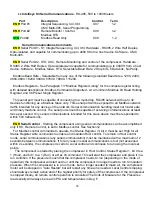
Digital Inputs
- 24 Vdc internally supplied source, 200ma max,
DI #1 = 140 ma., DI #2 - #7 = 10 ma., DI #8 = 1.4 ma. typical current.
Input Fault Description Control Term
STD
#1 Open Emergency Stop X04 1-2
ENH
#2 Closed Oil Filter Condition X04 1-3
ENH
#3 Closed Inlet Filter Condition X04 1-4
STD
#4 Open Motor Over load (Main, Fan, Dryer) X04 1-5
*
ENH
#5 Remote Start and Stop X04 1-6
*
ENH
#6 Remote Load Enable X04 1-7
*
ENH
#7 Remote Load/Unload X04 1-8
ENH
#8 Motor PTC X04 1-9
*
IEO
and ASC can control the compressors using an ISCII module
connected to digital inputs #5, #6 and #7.
1.4
Digital Outputs
- Internal relay, 24 Vdc @ 8 Adc, 240 Vac @ 8Aac
resistive,
Output Description Control Term
Control Voltage Input, DO #1- #3 X03 1
STD
#1 Starter Contact 1M X03 2-Comn
STD
#2 Starter Contact 1S X03 3-Comn
STD
#3 Load / Blowdown Solenoid Valve X03 4-Comn
Control Voltage Input, DO #4 X03 5
ENH
#4 Modulation X03 6-Comn
STD
#5 Condensate Drain X02 1-2
STD
#6 General Alarm Contact (NO) X02 3-4
Digital Output Comments
STD
Star Delta Logic Using Two Digital Outputs -
Combine 1M / 2M on one common output, a
normally closed electrical interlock (KM3-2) from the 1S (KM3) contactor keeps the 2M (KM2)
contactor from energizing anytime the 1S (KM3) contactor is energized.
Electrical interlocks are wired such that when the 1S (KM3) output is de-energized at Star Delta
transition time causing the 1S (KM3) contactor to open, the 1S normally closed interlock (KM3-2) falls
back to the closed position energizing the 2M (KM2) contactor.
A second electrical interlock from the 1S (KM3) contactor is wired in series with the 1M (KM1)
contactor to insure the 1S (KM3) is pulled in before the 1M (KM1) will be energized. An interlock from
the 1M (KM1) contactor is used to seal around the 1S (KM3-1) contact to allow the 1M (KM1) contact
to remain energized when the 1S (KM3 contact is de-energized at the Star Delta transition.
STD
Allen Bradley SMC-3 Soft Start Logic Using Two Digital Outputs
Outputs X03-2 and X03-3 can be configured to operate an Allen Bradley SMC-3 soft starter. The
operating sequence of X03-2 and X03-3, when the soft starter starting method is selected, follows.
X03-3 energizes immediately at the start command. 1/2 seconds later X03-2 energizes. Both outputs
maintain an energized state while the motor is given a run signal. When the motor is given a stop
signal the operating sequence of X03-2 and X03-3 are reversed from the starting sequence.
Summary of Contents for R110IU-10
Page 5: ...5 S3 Intellisys Controller Operating Instructions...
Page 6: ...6 Software Navigation...
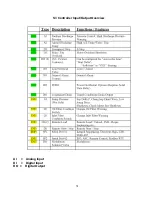
Page 7: ...7 Eiger Controller Fault Indicators 020 Tr Motor PTC Open High Motor Temperature...
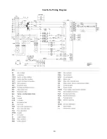
Page 14: ...14 Star Delta Wiring Diagram...
Page 15: ...15...
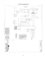
Page 16: ...16 Soft Start Wiring Diagram...
Page 17: ...17...
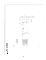
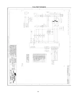
Page 18: ...18 Line Start Schematic...
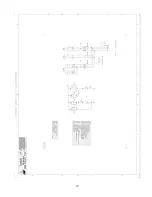
Page 19: ...19...
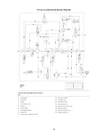
Page 20: ...20 Process and Instrumentation Diagram...
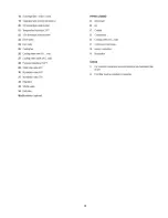
Page 21: ...21...
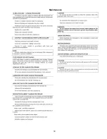
Page 28: ...28 Maintenance...
Page 29: ...29 Maintenance...
Page 30: ...30 Maintenance...
Page 31: ...31 S3 Controller Input Output Overview AI Analog Input DI Digital Input DO Digital Output...
Page 45: ...45 Standard S3 Menu Structure and Parameters Table 12...
Page 46: ...46 Standard S3 Menu Structure and Parameters Table 12...
Page 47: ...47 Standard S3 Menu Structure and Parameters Table 12...
Page 49: ...49 Modbus Register Listing...
Page 50: ...50 Table 13 Modbus Register Listing...
Page 52: ...52 Appendix 1 Thermistor 2ATT 34 to 124 C 255 F Air end Discharge...
Page 53: ...53...
Page 54: ...54...
Page 55: ...55...
Page 56: ...56...
Page 57: ...57...
Page 58: ...58 General Specifications for Eiger Packages...
Page 59: ...59...
Page 60: ...60...
Page 61: ...61...
Page 62: ...62...
Page 63: ...63...
Page 64: ...64...
Page 65: ...65...
Page 66: ...66...
Page 67: ...67...
Page 68: ...68...
Page 69: ...69...
Page 70: ...70...
Page 71: ...71...
Page 72: ...72...
Page 73: ...73...
Page 74: ...74...
Page 75: ...75...
Page 76: ...76...
Page 77: ...77...
Page 78: ...78...
Page 79: ...79...

