Operating & Maintenance Manual
SECTION 5 - OPERATION
46
Speed and Pressure Regulator Adjusting Instructions
The engine idle and full speed settings are
set and sealed at the factory, and should not
be adjusted. Serious injury may result if the
full speed is increased. Removal of the seals
without authorization could affect the
warranty. If speed settings are lost due to
engine fuel pump service or other repairs, the
speed settings can be reset as follows:
Before Starting
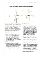
1. At the Pressure Regulator (on service
pipe near receiver tank), remove the
cover to expose the adjusting screw.
Loosen the jam nut and turn screw
counterclockwise until tension is no
longer felt at the screw. Then, turn screw
clockwise one full turn.
2. Close service valve(s).
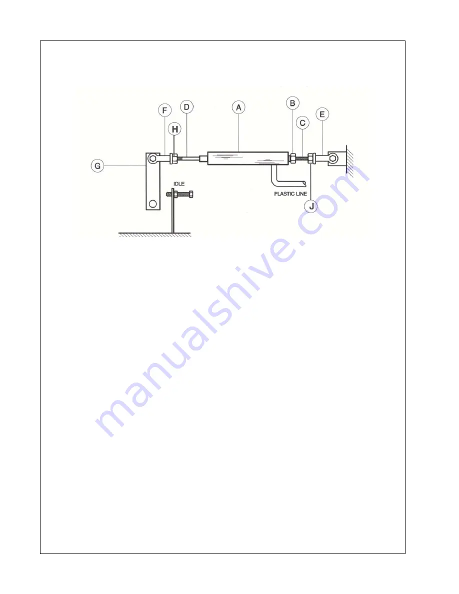
3. Inspect throttle arm (G) on engine
governor to see the arm is resting against
the governor stop. Loosen jam nut on air
actuating cylinder (A) and then turn
cylinder rod (D) until throttle arm (G) is
forced against the governor stop.
After Starting Unit
4. If equipped, push the SERVICE AIR
button on the control panel, making
certain the button does not pop back out.
The unit should speed up and then
unload (and drop back to IDLE). With the
unit unloaded, turn the adjusting screw
on the pressure regulator clockwise until
the discharge pressure gauge indicates
125-130 psi. Tighten the pressure
regulator jam nut. Replace cover.
5. With the service valve closed, adjust
IDLE speed (*). Adjust speed using
adjusting rod (D). Tighten jam nut (H).
6. Open the service valve and adjust the
discharge pressure to 100 psi (700 kPa).
Now turn adjusting rod (C) until the
proper engine FULL speed setting (*) is
reached. Tighten jam nuts (B & J).
7. To obtain maximum CFM at any pressure
between 80 psi (550kPa) and maximum
pressure rating (*), make adjustment at
the pressure regulator to obtain desired
discharge pressure at FULL engine
speed. Lock adjusting screw and replace
cover.
* See General Data Specifications.
Summary of Contents for P185AWIR
Page 6: ...1 4...
Page 7: ...3 FOREWORD...
Page 8: ...4...
Page 10: ...6...
Page 11: ...7 DRAWBAR NOTICE...
Page 12: ...Operating Maintenance Manual 8...
Page 14: ...Operating Maintenance Manual 10...
Page 15: ...11 Section 1 Safety...
Page 19: ...Safety Operating Maintenance Manual 15...
Page 20: ...Operating Maintenance Manual Safety 16...
Page 22: ...Operating Maintenance Manual Safety 18...
Page 23: ...Safety Operating Maintenance Manual 19...
Page 25: ...21 Section 2 WARRANTY...
Page 30: ...Operating Maintenance Manual WARRANTY 26...
Page 32: ...Operating Maintenance Manual WARRANTY 28...
Page 33: ...29 Section 3 NOISE EMISSION...
Page 39: ...35 Section 4 GENERAL DATA...
Page 42: ...Operating Maintenance Manual GENERAL DATA 38...
Page 43: ...39 SECTION 5 OPERATION...
Page 51: ...47 Section 6 MAINTENANCE...
Page 59: ...55 Section 7 LUBRICATION...
Page 61: ...57 Section 8 Trouble Shooting...

