


INSTALLATION / HANDLING
22
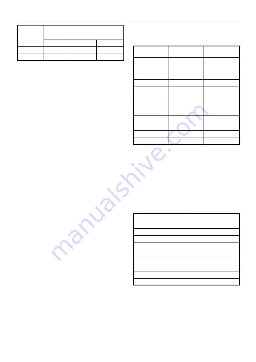
M200–LV M250–LV
Model Range
Minimum cooling water requirement at ambient
temperatures, in litres per minute (UK gallons per
minute)
50
_
F / 10
_
C
70
_
F / 21
_
C
90
_
F / 32
_
C
M200
91(20)
110(24)
180(40)
M250
114(25)
158(35)
246(54)
Water temperature and pressure gauges should be installed in the
water piping for use in any fault finding of the water system. Water
pressure should ideally be between 3 and 5 bar.
Water cleanliness is also extremely important. Cleaning of coolers as
a result of fouling is a customer responsibility. Therefore, it is highly
recommended that proper water quality must meet the requirements
listed in WATER QUALITY RECOMMENDATIONS later in this section.
Venting the water system
At the initial installation or for start–up after draining the water system
proceed to vent the system as follows
1 Locate the water system vent cocks on top of the aftercooler and
lubricant cooler.
2 Open the water valve(s) allowing water to flow to the package.
3 Open the vent cocks and allow all air to escape from the system.
When water is observed at the vent cocks, close them
The system is now vented.
Draining the water system
Should it become necessary to completely drain the water system,
proceed as follows.
1 Disconnect the inlet and discharge water lines from the connections
located at the rear of the unit.
2 Locate the aftercooler and lubricant cooler. Remove the drain plugs
located at the bottom of the coolers. Allow the system to completely
drain.
Water quality recommendations
Water quality is often overlooked when the cooling system of a
water–cooled air compressor is examined. Water quality determines
how effective the heat transfer rate, as well as the flow rate will remain
during the operation life of the unit. It should be noted that the quality
of water used in any cooling system does not remain constant during
the operation of the system. Evaporation, corrosion, chemical and
temperature changes, aeration, scale and biological formations effect
the water makeup. Most problems in a cooling system show up first in
a reduction in the heat transfer rate, then in a reduced flow rate and
finally with damage to the system.
Scale: Scale formation inhibits effective heat transfer, yet it does help
prevent corrosion. Therefore, a thin uniform coating of calcium
carbonate is desired on the inner surface. Perhaps the largest
contributor to scale formation is the precipitation of calcium carbonate
out of the water. This is dependent on temperature and pH. The higher
the pH value, the greater the chance of scale formation. Scale can be
controlled with water treatment.
Corrosion: In contrast to scale formation is the problem of corrosion.
Chlorides cause problems because of their size and conductivity. Low
pH levels promote corrosion, as well as high levels of dissolved
oxygen.
Fouling: Biological and organic substances (slime) can also cause
problems, but in elevated temperature environments such as cooling
processes they are not a major concern. If they create problems with
clogging, commercial shock treatment are available.
To ensure good operation life and performance of the compressor
cooling system, the recommended acceptable ranges for different
water constituents are included below:
Cooling Water Analyses Chart
Substances
Test interval
Acceptable
concentration
Corrosivity (Hard-
ness, pH, Total Dis-
solved Solids, Tem-
perature at inlet Alka-
linity)
Monthly — if stable
for 3 to 4 months,
analyse quarterly.
Langelier Index 0 to 1
Iron
Monthly
<2 ppm
Sulphate
Monthly
<50 ppm
Chloride
Monthly
<50 ppm
Nitrate
Monthly
<2 ppm
Silica
Monthly
< 100 ppm
Desolated Oxygen
Daily
— if
stable,analyse
weekly
0 ppm (as low
aspossible)
Oil & Grease
Monthly
<5 ppm
Ammonia
Monthly
<1 ppm
The Ingersoll–Rand Hydro–check cooling water analysis kit
CPN89223481 provides a sample bottle and pre–addressed return
tube to our laboratory, where a full report on water quality will be issued.
SEA WATER COOLED UNITS
Sea Water Pressure in Bars
Orifice diameter in mm to give a
maximum sea water flow of
340l/min
3 bar
23
4 bar
21
5 bar
20
6 bar
19
7 bar
18
8 bar
17
9 bar
17
10 bar
16
Water cleanliness is also extremely important. Strainers are available
from Ingersoll–Rand. Cleaning of coolers as a result of fouling is a
customer responsibility.
Isolation valves with side drains should be installed on both the inlet and
outlet lines.
It is recommended that a normally closed solenoid valve be fitted to the
water outlet side of the compressor package.