


INSTALLATION / HANDLING
21
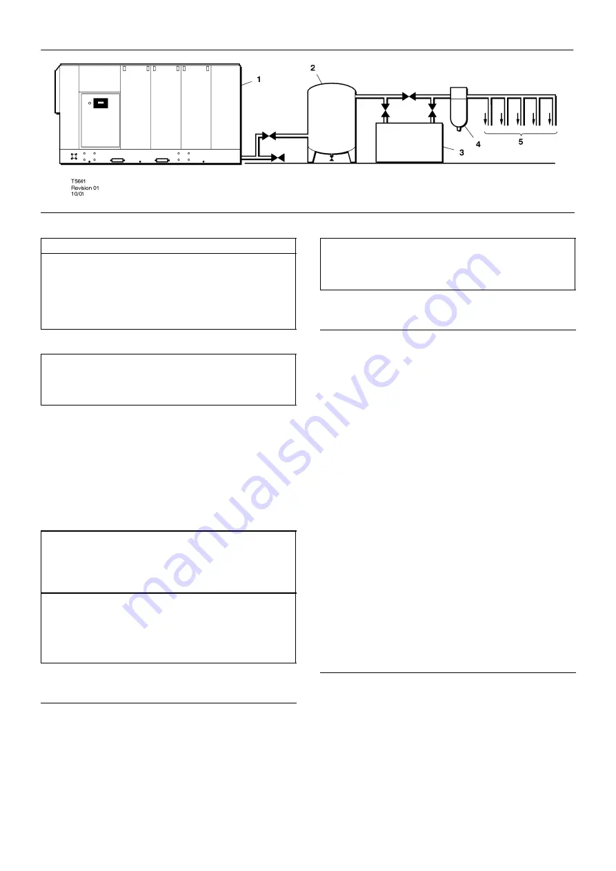
M200–LV M250–LV
KEY
1. Compressor
2. Air Receiver
3. Air Dryer
4. Compressed air filters
5. System demand points
NOTE
Items [2] to [5] are optional or may be existing items of plant. Refer
to your Ingersoll–Rand distributor / representative for specific
recommendations.
Hard surfaces may reflect noise with an apparent increase in the
decibel level. When sound transmission is important, a sheet of rubber
or cork can be installed beneath the machine to reduce noise.
It is recommended that provision be made for lifting heavy
components during major overhaul.
CAUTION
Screw type compressors [1] should not be installed in air systems
with reciprocating compressors without means of isolation such as a
common receiver tank. It is recommended that both types of
compressor be piped to a common receiver using individual air lines.
CAUTION
The use of plastic bowls on line filters and other plastic air line
components without metal guards can be hazardous. Their safety can
be affected by either synthetic coolants or the additives used in mineral
oils. From a safety standpoint, metal bowls should be used on any
pressurised system.
DISCHARGE PIPING
Discharge piping should be at least as large as the discharge
connection of the compressor. All piping and fittings should be suitably
rated for the discharge pressure.
It is essential when installing a new compressor [1], to review the
total air system. This is to ensure a safe and effective total system. One
item which should be considered is liquid carryover. Installation of air
dryers [3] is always good practice since properly selected and installed
they can reduce any liquid carryover to zero.
It is good practice to locate an isolation valve close to the
compressor and to install line filters [4].
NOTE
After the machine has been sited, remove the four transportation
bolts and spacers which are marked with fluorescent tags. Two are
situated on the airend support and the other two on the motor support.
ELECTRICAL DATA
An independent electrical isolator should be installed adjacent to the
compressor.
Feeder cables should be sized by the customer/electrical
contractor to ensure that the circuit is balanced and not overloaded by
other electrical equipment. The length of wiring from a suitable
electrical feed point is critical as voltage drops may impair the
performance of the compressor.
The applied voltage must be compatible with the motor and
compressor data plate ratings.
The control circuit transformer has different voltage tappings.
Ensure that these are set for the specific applied voltage prior to
starting.
Feeder cable connections to studs L1–L2–L3 on isolator should be
tight and clean.
CAUTION
Never test the insulation resistance of any part of the machines
electrical circuits, including the motor without completely disconnecting
the intellisys controller.
NOTICE
Fuses F1 and F2 are supplied loose in the starter cabinet. Do not
install until all electrical testing has been completed.
WATER COOLED UNITS
Cooling Water Piping
Water piping to and from the compressor package must be 2”diameter
or larger. Isolation valves with side drains should be installed on both
the inlet and outlet lines. Also a strainer of 3mm–mesh size should be
installed on the inlet line. Strainers are available from Ingersoll–Rand.
Ingersoll–Rand CPN 54690060.
It is recommended that a normally closed solenoid valve be fitted to the
water outlet side of the compressor package. This is to be wired into the
compressor control circuit. This option detail is available from
Ingersoll–Rand.
Carefully inspect your water system before installing the compressor
package. Ensure that the piping is free of scale and deposits that may
restrict water flow to the compressor package.
Proper operation of your compressor requires that the water flow listed
below be provided at a maximum supply temperature of 32
_
C