


8
inlet. Supply lines should be as short and straight as installation
conditions will permit. Long transmission lines and excessive
use of fittings, elbows, tees, globe valves, etc. cause a reduction
in pressure due to restrictions and surface friction in the lines.
Air Line Lubricator
The air motor may be operated without lubrication. If an air line
lubricator is used, it should be replenished daily with SAE 30W
Grade ISO VG 100 oil (minimum viscosity 135 Cst at 104° F
(40° C)).
CAUTION
• Shut off air supply before filling air line lubricator.
Air Line Filter
It is recommended that an air line strainer/filter be installed
within 3 ft (1 m) of the motor air inlet port to prevent dirt from
entering the motor. The strainer/filter should provide 20 micron
filtration and include a moisture trap. Clean the strainer/filter
monthly to retain its operating efficiency.
Moisture in Air Lines
Moisture that reaches the air motor through the supply lines is
the chief factor in determining the length of time between
service overhauls. Moisture traps can help eliminate moisture.
Other methods, such as an air receiver which collects moisture
before it reaches the motor, or an aftercooler at the compressor
that cools the air prior to distribution through the supply lines,
are also helpful.
Motor
For optimum performance and maximum durability of parts,
operate the air motor within the operating specifications
provided in the "SPECIFICATIONS" section. The air motor
should be installed as near as possible to the compressor or air
receiver.
Overload Device
(Optional feature)
Overload protection is integrated into the motor body and is
standard on -E versions. The overload system is based on
detection of the difference in air pressure between the inlet and
outlet ports. It consists of a valve which is normally closed. The
valve senses pressure at the motor inlet and outlet and compares
the difference between the two pressures to the index value
established by spring adjustment. A difference in pressure
greater than the index value causes the emergency stop to be
activated. This then exhausts the air and hoist operation stops.
Overload protection is adjusted at the factory to 120% of the
safe working load (SWL). It is also able to operate on both sides
for mining versions with two bottom hooks. Refer to the
"MAINTENANCE" section for adjustment procedures.
Main Air Shut-off Valve
The main air shut-off valve is completely integrated into the
motor body and is standard on -E versions.
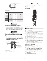
Chain Container
Refer to Dwgs. MHP1441 or MHP1442 in the "PARTS" section.
1.
Check the chain container size to make sure the length of
the load chain is within the capacity of the chain
container. Replace with a larger chain container if required.
2.
When a chain bucket is used, always connect the free end
of the chain to the hoist. Install a chain buffer on the ninth
link from the end of the chain.
3.
Attach the chain container to the hoist.
4.
Run bottom block to the lowest point and run hoist in the
"UP" direction to feed the chain back into the container.
NOTICE
• Make certain to adjust the balance chain so that the chain
container does not contact the load chain.
• Allow chain to pile naturally in the chain container. Piling
the chain carelessly into the container by hand may lead to
kinking or twisting that will jam the hoist.
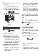
Pendant
Check that all hose connections are tight and that hoses are not
twisted or crimped. Refer to Dwg. MHP1506 for hose
connections. Pendant lengths up to 66 ft (20 m) are available.
Contact the factory for pendant lengths greater than 66 ft (20 m).
CAUTION
• To avoid damaging the pendant hose, make sure the strain
relief cable, not the pendant hose, is supporting the weight of
the pendant.
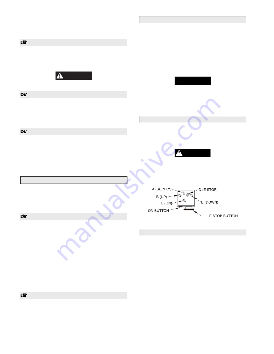
Single Motor Pendant PHS2E(-U) (Top View)
(Dwg. MHP1506)
Storing the Hoist
1.
Always store the hoist in a no load condition.
2.
Wipe off all dirt and water.
3.
Oil the chain, hook pins and hook latch.
4.
Place in a dry location.
5.
Plug hoist air inlet port.
6.
Before returning hoist to service, follow instructions for
hoists not in regular service in the "INSPECTION" section.
Summary of Contents for LCA015
Page 26: ...25 SERVICE NOTES ...
Page 27: ...26 SERVICE NOTES ...
Page 31: ...30 LCA030S AND LCA060D HOIST ASSEMBLY PARTS DRAWING 3 and 6 ton Hoist Capacities Dwg MHP1464 ...
Page 33: ...32 LCA060S AND LCA120D HOIST ASSEMBLY PARTS DRAWING 6 and 12 ton Hoist Capacities Dwg MHP1465 ...
Page 50: ...49 SERVICE NOTES ...


