


22
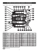
LCA030S and LCA060D Hoists
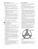
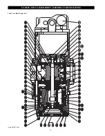
Refer to Dwg. MHP1464.
1.
Lubricate and install 'O' rings (30) and (33) on brake piston
(29) and brake cover (35).
2.
Install brake piston (29) with 'O' rings in gear housing (31).
3.
Using a small amount of grease on each spring (34)
position springs in the brake cover spring holes and install
brake cover (35) on gear housing (31). Install and tighten
six cover screws (32), one half turn at a time each, until
cover is secure. Keep brake cover square to gear housing
during installation to avoid damaging 'O' ring (33).
4.
Install plug (7) and copper washer (8) in brake cover (35).
5.
Reinstall handle (37) if previously removed.
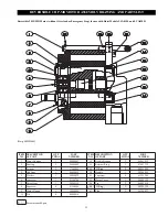
LCA060S and LCA120D Hoists
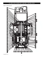
Refer to Dwg. MHP1465.
1.
Lubricate 'O' rings (8) and (32) and install on brake cover
(37) and brake piston (33).
2.
Install brake sleeve (39) on sun gear (41) and secure in
position with retainer ring (36).
3.
Install brake piston (33).
4.
Using a smal amount of grease on each spring (38),
position springs in the brake cover spring holes and install
brake cover (37) on gear housing (30). Install and tighten
six cover screws (31), one half turn at a time each, until
cover is secure. Keep brake cover square to gear housing
during installation to avoid damaging 'O' ring.
5.
Install plug (34) and seal washer (35) in cover (37).
6.
Reinstall handle (28) if previously removed.
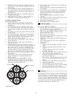
Motor
2HP without Emergency Stop or Overload
Refer to Dwg. MHP1458.
1.
Lubricate bearings (2) with Grade 2 grease then install
bearings in motor flange (9). Ensure markings on bearing
cage are still visible after installation.
2.
Install washer (5) and capscrew (6) to retain bearings.
Lightly coat capscrew threads with Loctite
®
234.
3. Install idle gear (4) and drive gear (7) through bearings in
motor flange (9).
4.
Immobilize the idle gear (4) and drive gear (7) with a rod
between the teeth. Install and tighten locknuts (3). Lightly
coat locknut threads with Loctite
®
234.
5.
Install motor housing (1) on motor flange.
6.
Lubricate and install quad rings (23) on slide valves (25).
Lubricate and install quad ring (24) in bore of gear housing
(1).
7.
Install rear stops (10), springs (11) and slide valves (25) in
gear housing.
8.
Position stop (18) in recess in motor cover (22). Install
needle bearings (14) in motor cover (22).
9.
Lubricate and install 'O' rings (19) in gear housing.
Carefully install motor cover assembly on gear housing
until fully seated. Ensure pins (12) are aligned and fully
engaged.
10. Lightly coat capscrew threads with Loctite
®
234 then install
and torque capscrews (8) to 7.5 ft-lbs (5.5 Nm). After
assembly of the motor, check to ensure motor driving gear
rotates freely in both directions.
11. Install motor assembly in motor housing (60). Secure in
position with four capscrews (21). Torque capscrews to 7.5
ft-lbs (5.5 Nm).
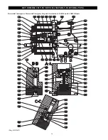
2HP with Emergency Stop and Overload
Refer to Dwg. MHP1467.
Follow steps 1 through 11 immediately above, for initial motor
assembly.
Assembly of Emergency Stop and Overload options:
1.
Ensure dowels (12) are installed in motor cover (22).
2.
Lubricate and position 'O' rings (13) and stops (18) on
motor cover.
3.
Assemble items (31), (32), (33) and (37) on screw (30).
Install screw with parts into motor cover. Screw (32), (33)
and (35) on opposite end and tighten. Use Loctite
®
243 on
threads.
4.
Install spring (28) and 'O' ring (29) in cover (27) and
assemble on motor cover. Secure with three capscrews
(36). Apply Loctite
®
243 to threads.
5.
Install diaphragm (34) on opposite side.
6.
Grease and install ball (52), spring receiver (42) and spring
(43) in motor cover.
7.
Assemble items (47), (44) and (45) to diaphragm (46).
Ensure parts are assembled from the correct side. There is
one extra hole in addition to the four capscrew holes. The
extra hole must align with the port hole in the motor cover
and cover (38).
8.
Install cover (38) with capscrews (39) and (54) using
Loctite
®
243 on the threads. Torque capscrews to 7.5 ft-lbs
(5.5 Nm).
9.
Install seal washer (49) in cover (38) with plug (50).
10. Thread nut (41) onto screw (40) and install with seal ring
(51).
11. Refer to Overload Device Adjustments in the
"MAINTENANCE" section to reestablish settings.
4HP without Emergency Stop or Overload
Refer to Dwg. MHP1457.
1.
Lubricate bearings (10) and (2) with Grade 2 grease then
install bearings in motor housing (14). Ensure markings on
bearing cage are still visible after installation.
2.
Install washer (5) and screw (6) to retain bearings. Lightly
coat screw threads with Loctite
®
234.
3.
Install 'O' ring (12) on shuttle valve stop (11). Install ball
(13) and screw shuttle valve stop into motor housing (14).
4. Install idle gear (15) and drive gear (4) through bearings in
motor housing (14).
5.
Immobilize the idle gear (15) and drive gear (4) with a rod
between the teeth. Install and tighten locknuts (3) and (9).
Lightly coat locknut threads with Loctite
®
234.
6.
Lubricate and install quad rings (29) on slide valves (16).
Lubricate and install quad ring (1) in bore of motor housing
(14).
7.
Install rear stops (7), springs (8) and slide valves (16) in
motor housing.
8.
Install bearing (23) on smaller stepped diameter of idle gear
(15). Secure in position with retainer ring (24).
9.
Position rear stops (28) in recess in motor cover (21).
Install needle bearing (30) in motor cover (21).
10. Lubricate and install 'O' rings (27) in motor cover.
Carefully install motor cover assembly on motor housing
until fully seated. Ensure pins (19) are aligned and fully
engaged.
11. Lightly coat capscrew threads with Loctite
®
234 then
install and torque capscrews (17) to 16.3 ft-lbs (12 Nm).
After assembly of the motor, check to ensure motor driving
gear rotates freely in both directions.
12. Install motor assembly in motor housing (60). Secure in
position with six capscrews (20) and (32). Verify capscrew
lengths for correct positioning.
Summary of Contents for LCA015
Page 26: ...25 SERVICE NOTES ...
Page 27: ...26 SERVICE NOTES ...
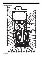
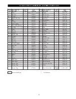
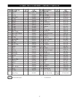
Page 31: ...30 LCA030S AND LCA060D HOIST ASSEMBLY PARTS DRAWING 3 and 6 ton Hoist Capacities Dwg MHP1464 ...
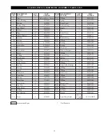
Page 33: ...32 LCA060S AND LCA120D HOIST ASSEMBLY PARTS DRAWING 6 and 12 ton Hoist Capacities Dwg MHP1465 ...
Page 50: ...49 SERVICE NOTES ...


