


17
MAINTENANCE
WARNING
• Never perform maintenance on the hoist while it is
supporting a load.
• Before performing maintenance, tag controls:
DANGER - DO NOT OPERATE -
EQUIPMENT BEING REPAIRED.
• Only allow personnel trained in operation and service of
this hoist to perform maintenance.
• After performing any maintenance on the hoist
dynamically test the hoist to 100% of its rated capacity, in
accordance with ASME B30.16 standards, before returning
hoist to service. Testing to more than 100% of rated capacity
is required to set overload device and may be required to
comply with standards and regulations set forth in areas
outside the USA.
• Shut off air system and depressurize air lines before
performing any maintenance.
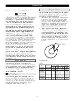
Proper use, inspections and maintenance increase the life and
usefulness of your Ingersoll-Rand equipment. During
assembly, lubricate gears, bearings and shafts with applicable
lubricants. Use of a thread locking compound and/or thread
lubricant on capscrew and nut threaded areas helps prevent
corrosion of components.
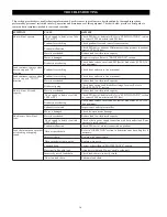
Maintenance Intervals
The Maintenance Interval Chart below is based on intermittent
operation of equipment for eight hours each day, five days per
week. If the equipment is in operation for more than eight hours
a day or is operated in severe applications or environments,
more frequent maintenance should be performed.
L
A
V
R
E
T
N
I
K
C
E
H
C
E
C
N
A
N
E
T
N
I
A
M
t
f
i
h
s
h
c
a
e
f
o
t
r
a
t
S
e
h
t
f
o
n
o
i
t
c
e
p
s
n
i
l
a
u
s
i
v
h
g
u
o
r
o
h
t
a
e
k
a
M
t
s
i
o
h
e
h
t
e
t
a
r
e
p
o
t
o
n
o
D
.
e
g
a
m
a
d
r
o
f
t
s
i
o
h
.
d
n
u
o
f
s
i
e
g
a
m
a
d
f
i
t
s
u
m
t
s
i
o
H
.
s
n
o
i
t
c
e
r
i
d
h
t
o
b
n
i
e
t
a
r
e
p
O
g
n
i
d
n
i
b
,
g
n
i
k
c
i
t
s
t
u
o
h
t
i
w
y
l
h
t
o
o
m
s
e
t
a
r
e
p
o
.
s
e
s
i
o
n
l
a
m
r
o
n
b
a
r
o
.
e
k
a
r
b
e
h
t
f
o
n
o
i
t
a
r
e
p
o
e
h
t
k
c
e
h
C
y
l
r
e
t
r
a
u
Q
f
o
p
o
t
n
i
r
e
l
f
f
u
m
e
c
a
l
p
e
r
r
o
n
a
e
l
c
,
e
v
o
m
e
R
.
g
n
i
s
u
o
h
r
a
e
g
y
l
r
a
e
Y
d
n
a
s
t
f
a
h
s
,
g
n
i
r
a
e
g
t
s
i
o
h
e
h
t
t
c
e
p
s
n
I
r
o
r
i
a
p
e
R
.
r
a
e
w
r
o
e
g
a
m
a
d
r
o
f
s
g
n
i
r
a
e
b
.
y
r
a
s
s
e
c
e
n
s
a
e
c
a
l
p
e
r
.
s
r
e
b
m
e
m
g
n
i
t
r
o
p
p
u
s
e
h
t
f
o
l
l
a
k
c
e
h
C
.
d
e
r
i
u
q
e
r
s
a
e
c
a
l
p
e
r
r
o
r
i
a
p
e
R
Adjustments
Brake
No brake adjustment is required.
Annual Maintenance is limited to:
1.
A general cleaning.
2.
The friction discs have a 0.2 mm (0.079 in.) deep groove on
each side. Replace the friction discs if the grooves are no
longer visible. Refer to Dwgs. MHP1415 and MHP1416.
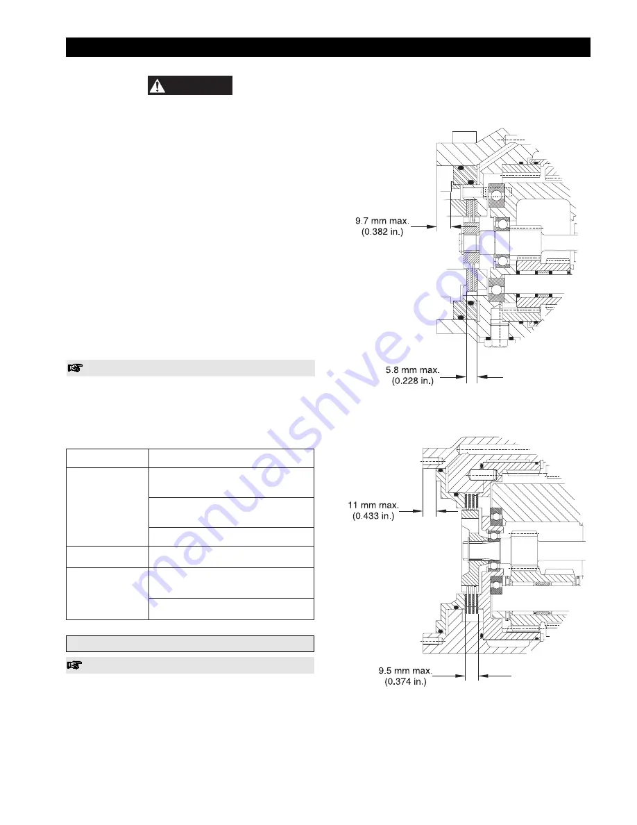
3.
Measure total brake and steel plate stack up. Check that
measurement is not below minimum shown.
LCA015S and LCA030D Hoists
(Dwg. MHP1415)
LCA030S, LCA060S, LCA060D and LCA120D Hoists
(Dwg. MHP1416)
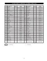
Summary of Contents for LCA015
Page 26: ...25 SERVICE NOTES ...
Page 27: ...26 SERVICE NOTES ...
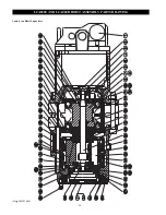
Page 31: ...30 LCA030S AND LCA060D HOIST ASSEMBLY PARTS DRAWING 3 and 6 ton Hoist Capacities Dwg MHP1464 ...
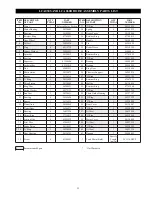
Page 33: ...32 LCA060S AND LCA120D HOIST ASSEMBLY PARTS DRAWING 6 and 12 ton Hoist Capacities Dwg MHP1465 ...
Page 50: ...49 SERVICE NOTES ...


