14
LUBRICATION
To ensure continued satisfactory operation of the hoist, all
points requiring lubrication must be serviced with the correct
lubricant at the proper time intervals indicated for each
assembly. Correct lubrication is one of the most important
factors in maintaining efficient operation.
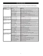
The lubrication intervals recommended in Table 6 are based on
intermittent operation of the hoist eight hours each day, five
days per week. If the hoist is operated almost continuously, or
for more than eight hours each day, or under severe conditions,
more frequent lubrication will be required.
6
e
l
b
a
T
t
n
e
n
o
p
m
o
C
l
e
v
e
L
e
g
a
s
U
y
b
y
c
n
e
u
q
e
r
F
n
o
i
t
a
c
i
r
b
u
L
e
r
e
v
e
S
y
v
a
e
H
l
a
m
r
o
N
n
i
a
h
C
d
a
o
L
y
l
i
a
D
y
l
k
e
e
W
e
g
a
s
U
t
A
d
n
a
k
o
o
H
h
c
t
a
L
k
o
o
H
y
l
i
a
D
y
l
k
e
e
W
e
g
a
s
U
t
A
e
s
a
C
r
a
e
G
y
l
r
a
e
Y
s
r
a
e
Y
3
y
r
e
v
E
y
r
a
s
s
e
c
e
n
n
U
Lubricant types and change intervals are based on operation in
an environment relatively free of dust, moisture and corrosive
fumes. Use only those lubricants recommended. Other lubricants
may affect performance of the hoist. Approval for the use of
other lubricants must be obtained from your Ingersoll-Rand
Technical Support Department or distributor. Failure to observe
this precaution may result in damage to the hoist and/or its
associated components.
Whenever a hoist is disassembled for overhaul or replacement of
parts, lubricate as follows:
Brake and Gear Assemblies
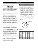
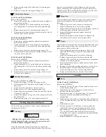
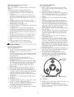
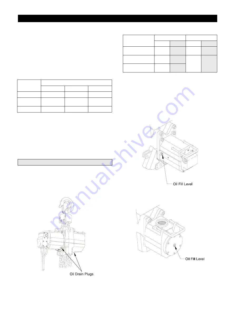
The gear and brake assemblies share a common oil bath. On
larger capacity hoists, the output shaft from the motor is offset
and utilizes a pinion gear to drive the sun gear. These gears
operate in the motor casing oil bath. Refer to Table 7 for oil
quantities. Refer to Dwg. MHP1473 for position of gear box oil
drain plugs.
(Dwg. MHP1473)
7
e
l
b
a
T
l
e
d
o
M
g
n
i
s
a
C
r
a
e
G
g
n
i
s
a
C
r
o
t
o
M
s
t
n
i
P
l
m
s
t
n
i
P
l
m
d
n
a
S
5
1
0
A
C
L
D
0
3
0
A
C
L
3
.
0
0
5
1
A
/
N
A
/
N
d
n
a
S
0
3
0
A
C
L
D
0
6
0
A
C
L
8
.
0
0
0
4
4
.
0
0
5
1
d
n
a
S
0
6
0
A
C
L
D
0
2
1
A
C
L
6
.
1
0
5
7
LCA015S and LCA030D Hoists Oil Fill Level Position
Fill to the level of the plug on the side of the gear housing.
LCA030S and Larger Hoists Oil Fill Level Position
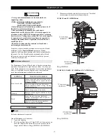
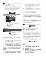
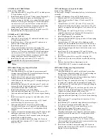
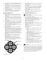
Fill to the level of the plug on the side of the motor housing and
on the gear end in the center of the brake end cover. Refer to
Dwgs. MHP1439 and MHP1440.
Oil Fill Level Position on Motor Housing
(Dwg. MHP1439)
Oil Fill Level Position on Brake End Cover
(Dwg. MHP1440)
Summary of Contents for LCA015
Page 26: ...25 SERVICE NOTES ...
Page 27: ...26 SERVICE NOTES ...
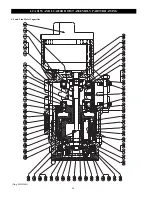
Page 31: ...30 LCA030S AND LCA060D HOIST ASSEMBLY PARTS DRAWING 3 and 6 ton Hoist Capacities Dwg MHP1464 ...
Page 33: ...32 LCA060S AND LCA120D HOIST ASSEMBLY PARTS DRAWING 6 and 12 ton Hoist Capacities Dwg MHP1465 ...
Page 50: ...49 SERVICE NOTES ...


