
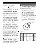


23
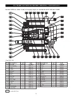
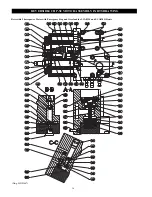
4HP with Emergency Stop and Overload
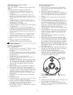
Refer to Dwg. MHP1455.
Follow steps 1 through 12 immediately above, for initial motor
assembly.
Assembly of Emergency Stop and Overload options:
1.
Ensure dowels (19) are installed in motor cover (21).
2.
Lubricate and position 'O' rings (27) and stops (28) on
motor cover.
3.
Assemble items (37), (38), (39) and (44) on screw (43).
Install screw with parts into motor cover. Screw (35), (37)
and (38) on opposite end and tighten. Use Loctite
®
243 on
threads.
4.
Install spring (42) and 'O' ring (46) in cover (45) and
assemble on motor cover. Secure with three capscrews (41).
Apply Loctite
®
243 to threads.
5.
Install diaphragm (36) on opposite side.
6.
Grease and install ball (50), spring receiver (51) and spring
(52) in motor cover.
7.
Assemble items (53), (54) and (55) to diaphragm (59).
Ensure parts are assembled from the correct side. There is
one extra hole in addition to the four capscrew holes. The
extra hole must align with the port hole in the motor cover
and cover (34).
8.
Install cover (34) with capscrews (32) using Loctite
®
243
on the threads. Torque capscrews to 7.5 ft-lbs (5.5 Nm).
9.
Install seal washer (57) in cover (34) with plug (58).
10. Thread nut (48) onto screw (47) and install with seal ring
(49).
11. Refer to Overload Device Adjustments in the
"MAINTENANCE" section to reestablish settings.
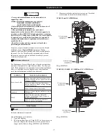
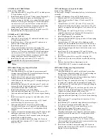
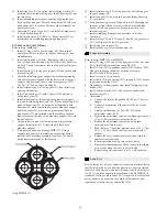
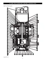
Reduction Housing
LCA015S and LCA030D Hoists
Refer to Dwg. MHP1462.
1.
Install 'O' ring (43) in gear housing (23). Ensure two dowel
pins (22) are in place in the gear housing and are
undamaged.
2.
Carefully install ring gear (20) in gear housing making sure
dowel pins are aligned with the holes in the ring gear. Tap
down until seated.
3.
Install bearing (40) on planetary support (19).
4.
Install two bearings (46) with a spacer (45) between, in
each planetary gear (44).
5.
Install planetary gears with bearings into planetary support
(19) and locate with satellite axles (47). Ensure planet gears
(44) are installed with the smaller gear head diameter
nearest the side of the planetary support (19) with the
timing notches.
6.
Rotate satellite axles to allow installation of bearing (17).
7.
Install bearing (39) and secure with retainer ring (32).
8.
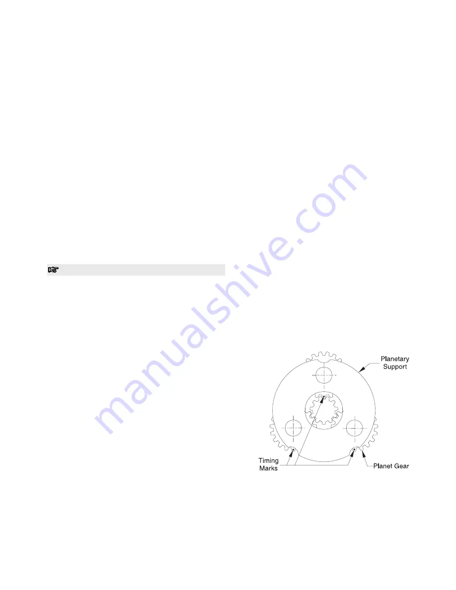
Time planetary gears as shown in drawing MHP1406. Use
of a separate ring gear tool to maintain gear position during
installation of planetary assembly is helpful. Install
planetary assembly and tap down until planetary assembly
is fully seated.
9.
Install pinion (21). Tap into position until seated against
bearing (39).
10. Install ring gear (18).
11. Lubricate and install 'O' ring (43) in gear cover (48). Install
oil seal (13) with lip toward planetary support.
12. Install gear cover (48). Attempt to locate the puller holes at
the top and bottom just off vertical. This may aid
disassembly at some later date. Install pinion (11).
13. Refer to "Brake Assembly" for information on assembling
the remaining brake parts.
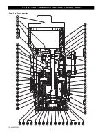
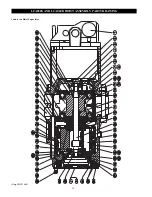
LCA030S and LCA060D Hoists
Refer to Dwg. MHP1464.
1.
Install 'O' ring (42) in gear housing (31). Ensure three
dowel pins (40) are in place in the gear housing (31) and
are undamaged.
2.
Install new 'O' ring (47) on ring gear (45).
3.
Install friction and steel discs. Begin with a friction disc
(27) and then alternate with a steel disc (28) until discs are
used. Locate friction disc tabs in slots provided in gear
housing.
4.
Install bearing (43) in ring gear and secure with retainer
ring (41).
5.
Carefully install ring gear in gear housing making sure
dowel pins are aligned with the holes in the ring gear. Tap
down until retainer ring groove in gear housing bore, is
visible. Use a clamp to further pull ring gear into position
compressing 'O' ring (42). Install retainer ring (48). Ensure
retainer ring is fully seated, then release clamp.
6.
Install sun gear (20) and tap into position through bearing
(43) until seated.
7.
Turn gear housing over and support to avoid damaging the
sun gear. Align tabs on steel discs (28) and install brake
sleeve (39) on sun gear spline. Secure in position with
retainer ring (36).
8.
Install two bearings (21) with a spacer (22) between, in
each planetary gear (24).
9.
Install planet gears with bearings into planetary support
(46) and locate with planet axles (23). Place one bearing
(25) and one thrust ring (26) on each side of the planetary
gears. Bearings (25) must contact inside face of planetary
support and thrust rings (26) must contact planet gears.
Ensure planet gears (24) are installed with the smaller gear
head diameter nearest the side of the planetary support (46)
with the timing notches.
10. Rotate planet axles to allow installation of bearing (44) on
the brake side. Pin punch around bearing to hold in place
during assembly into gear housing (31).
11. Time gears as shown in drawing MHP1406. Using a
separate ring gear tool to maintain gear position during
installation of planetary assembly is helpful. Tap down
until planetary assembly is fully seated.
(Dwg. MHP1406)
12. Install oil seal (57) and 'O' rings (54) and (56) on gear cover
(55). Seal lip must be toward gear side.
13. Set drive pinion (17) on bench with the splined end up.
Install gear cover on drive pinion with the threaded jacking
holes toward the bench.
Summary of Contents for LCA015
Page 26: ...25 SERVICE NOTES ...
Page 27: ...26 SERVICE NOTES ...
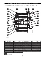
Page 31: ...30 LCA030S AND LCA060D HOIST ASSEMBLY PARTS DRAWING 3 and 6 ton Hoist Capacities Dwg MHP1464 ...
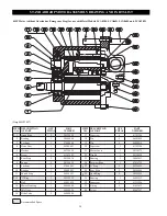
Page 33: ...32 LCA060S AND LCA120D HOIST ASSEMBLY PARTS DRAWING 6 and 12 ton Hoist Capacities Dwg MHP1465 ...
Page 50: ...49 SERVICE NOTES ...


