NOTICE
•
‘O’ ring (5) listed in step 13 refers to part number 51459 as shown on winch
assembly Dwg. MHP2948 in the Parts Information Manual. This part must
be placed between mounting flange (216) and motor adapter (6).
14. Install eye bolts (213) and vent cap assembly (210) in motor housing (217).
15. Ensure oil drain and level plugs (218) are installed.
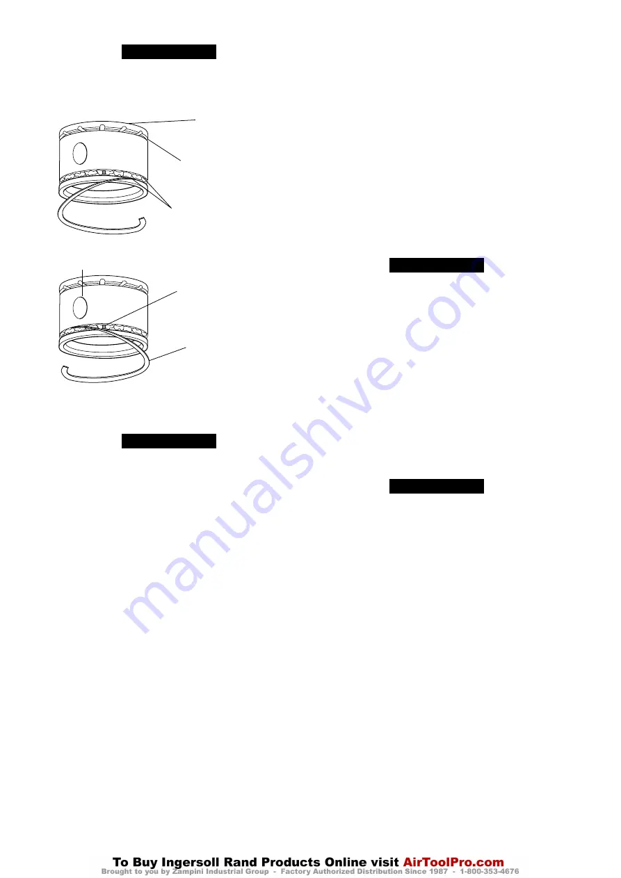
Piston Head
Wrist pin
opening
Install one wiper ring on
either side of oil ring
Ends of wiper rings must be
staggered to avoid alignment
with wrist pin opening and
ends of oil ring
Colored ends of oil ring
must butt together, and
must not overlap
Compression Ring Groove
(Dwg. MHP0224)
n
Reduction Gear Assembly
Refer to Dwg. MHP0875.
NOTICE
•
During assembly of components apply a light coat of Loctite® 242 to all
threaded fasteners. Clean all mating surfaces. ‘O’ rings can be held in place
with a coating of EP grease applied to groove.
•
It is extremely important to maintain a clean work area when reduction
gear assembly is reassembled. During reassembly clean each part
thoroughly and lightly coat with appropriate lubricant as described in
‘Recommended Lubricants’ of “LUBRICATION” section in the Product
Information Manual.
1. If removed, install planetary gears (415) into planetary support (410) as follows:
a. Install a pair of spring pins (412) into holes in planetary support (410).
b. Install and center roller spacer (416) in planet gear (415) bore.
c. Place 40 roller bearings (414) in each side of planet gear (415), a light coat
of grease will help to hold them in place. Place a thrust bearing (413) on each
side of planetary gear assembly and squeeze.
d. Depress one spring pin (412) and slide planetary gear assembly over it.
Depress other side and tip gear assembly into planetary support. Rotate gear
assembly around spring pins until shaft hole aligns.
e. Push planet gear shaft (417) into place. Repeat for remaining two gear
assemblies.
f. Ensure each planet gear (415) rotates freely, without sticking or binding.
2. Fasten thrust plate (449) to front cover (450) with screws (453) and loosely
tighten.
3. Place a new gasket (447) on end cover (446). Install capscrews (452) through
front cover (450), gasket (447) and into end cover (446) and tighten.
4. Lubricate and install new ‘O’ ring (442) into groove on end cover (446). Apply a
bead of Loctite® 515 sealant to mating surface.
5. Align ring gear (444) with spring pins (443) and press ring gear on end cover
(446). Apply a bead of Loctite® 515 sealant to mating surface.
6. Lubricate and install new ‘O’ ring (442) into input housing (438).
7. Slide shaft (445) into planetary assembly (440). Insert this assembly into ring gear
(444).
8. Align spring pins (443) with input housing (438) and press down.
9. Insert capscrews (448) through end cover (446) and into input housing (438).
Refer to “TORQUE CHART” on page 16 for torque requirements.
10. Lubricate and install new ‘O’ ring (434) into groove on input housing (438). Apply
a bead of Loctite® 515 sealant to mating surface.
11. Align ring gear (436) with spring pins (437) and press down.
12. Install retaining ring (435) onto sun gear (433) and slide down shaft (445) into
planetary assembly (440).
13. Install spacer (422) into sun gear (433).
14. Install planetary assembly (430) into ring gear (436).
15. Slide sun gear (429) onto shaft (445) and into planetary assembly (430). Insert
spacer (428) into sun gear (429).
16. Insert bearing (426) into input housing (424). Install retainer ring (427).
17. Lubricate and install new ‘O’ ring (434) into groove on input housing (424). Apply
a bead of Loctite® 515 sealant to mating surface.
18. Align spring pins (437) with input housing (424) and press down.
19. Insert capscrews (439) through input housing (438) and into input housing (424).
Refer to “TORQUE CHART” on page 16 for torque requirements.
20. Insert spacer (423) into input housing (424) with bevel facing housing.
21. Lubricate and install new ‘O’ ring (419) onto outer groove on spacer (418). Insert
spacer (422) into center recess in spacer (418). Place this assembly into planetary
support (410) from planet gear end.
22. Insert retainer ring (420) in planetary support to hold spacer assembly in place.
23. Lubricate and install new ‘O’ ring (408) into groove in input housing (424). Apply
a bead of Loctite® 515 sealant to mating surface.
24. Align ring gear (409) with spring pins (404) and push down.
25. Insert planetary support assembly into ring gear (409).
26. Lubricate and install new ‘O’ ring (408) into groove in support (405). Apply a bead
of Loctite® 515 sealant to mating surface.
27. Align support (405) with spring pins (404) and push down.
28. Insert capscrews (425) through input housing (424) into support (405). Refer to
“TORQUE CHART” on page 16 for torque requirements.
29. Insert ball bearing (407) into support (405).
30. Insert oil seal (402) into seal support (400) (lip facing out).
31. Lubricate and install new ‘O’ ring (403) in groove in support (405). Apply a bead
of Loctite® 515 sealant to mating surface.
32. Align bolt holes with seal support (400) and support (405).
33. Insert capscrews (401) through seal support, into support and tighten.
34. Turn adjusting screw (453) in until end play is eliminated, then back it out two
turns.
n
Drum Assembly
Refer to Dwgs. MHP2948 and MHP0875.
NOTICE
•
During assembly of components apply a light coat of Loctite® 242 to all
threaded fasteners.
•
Clean all mating surfaces. ‘O’ rings can be held in place with a coating of EP
grease applied to groove.
1. Position drum (96) in vertical position, with reduction gear side facing up.
2. Remove plugs (406) from reduction gear support (405). Apply a bead of Loctite®
515 sealant on reduction gear surface that mates with adapter (52).
3. Place adapter (52) on reduction gear and align bolt holes. There is one place on
adapter with no hole. This should be positioned over one of plug (406) holes.
This becomes the drain/fill location (other 3 plugs will be blocked). Install
capscrews (50) through adapter (52) and attach nuts (48). Refer to “TORQUE
CHART” on page 16 for torque requirements. With a hammer and punch, drive
spring pins (404) into adapter (52) until about 1/16 inch (1.5 mm) below surface.
4. Apply a bead of Loctite® 515 sealant to surface of drum (96) where adapter (52)
will mate.
5. Install two 1/2 inch - 13 NC x 2 inch capscrews with suitable lifting eyes into
threaded holes in outer bolt pattern ring of drum adapter (52). Lift reduction
gear assembly into drum (96). Align bolt holes and install capscrews (63) through
adapter (52) and into drum (96). Refer to “TORQUE CHART” on page 16 for
torque requirements.
6. Place drum in horizontal position.
n
Winch Assembly
Refer to Dwgs. MHP2948 and MHP2944.
NOTICE
•
During assembly of components apply a light coat of Loctite® 242 to all
threaded fasteners.
•
Clean all mating surfaces. ‘O’ rings can be held in place with a coating of EP
grease applied to groove.
1. Install bearing (188) in outboard upright (184).
2. Install outboard upright (184) on drum end. Ensure assembly is kept centered
on journal during this step.
3. Install bearing retainer (191). Secure with capscrews (192). Refer to “TORQUE
CHART” on page 16 for torque requirements.
4. Apply a bead of Loctite® 515 sealant to mating surface of outboard upright (184)
and install end cover (193). Secure with capscrews (582) and washers (306). Refer
to “TORQUE CHART” on page 16 for torque requirements.
5. Lubricate and install ‘O’ ring (43) on drum shaft (41).
6. Insert drum shaft (41) into inboard upright (42), aligning dowel pin holes.
7. Install dowel pins (62) flush or slightly below surface of drum shaft (41).
8. Install capscrews (39). Refer to “TORQUE CHART” on page 16 for torque
requirements.
9. Install inboard upright (42) onto reduction gear input shaft. Ensure splines on
drum shaft (41) align with splines in reduction gear.
10. Install siderails (98) to uprights (42) and (184) and loosely secure using capscrews
(119) and washers (117).
11. Tap dowel pins (183) into position until flush with siderails.
12. Tighten capscrews (119) evenly. Refer to “TORQUE CHART” on page 16 for
torque requirements.
13. Lightly coat input shaft (7) with Loctite® 609 and press bearing (37) onto input
shaft (7). Install retainer ring (38).
14. Insert retainer ring (45) into middle of coupling (49). Place onto reduction gear
end of input shaft (7).
15. Install input shaft assembly into drum shaft (41). Install retainer ring (36) in bore
of drum shaft (41).
Instructions 16 through 27 cover winches with a disc brake. For winches
without a disc brake skip to instruction 28.
16. Slide splined hub (19) onto input shaft (7), gear teeth side in first. Install retainer
ring (38).
17. Place seven friction plates (16) and eight drive plates (17) onto splined hub (19).
Lubricate all plates with ISO VG 46 (SAE 10W) oil, starting with a drive plate (17),
then friction plate (16) until all plates are used.
12
Form MHD56401 Edition 3


