18. Locate brake port. This should be 45 degrees to the right of top center. There
are two other ports which should be straight up and straight down (one becomes
the drain, the other becomes a vent).
19. Install pipe plug (24) into lower port in brake housing (21). Install reducer bushing
(22) and breather (23) into top port on brake housing (21).
20. Slide brake housing (21) over brake plates. Apply a coating of ISO VG 100 (SAE
3EP) oil to inside surface of brake housing (21).
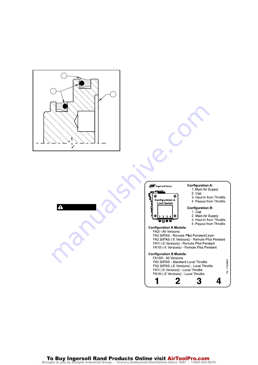
21. Lubricate and install seals (11) and (12) in brake piston (10) grooves so lips face
each other. Do not over stretch seals during this procedure. Refer to Dwg.
MHP0139 on page 13, A. Seal Lip; B. Seal; C. Brake Piston.
22. Install brake piston assembly into brake housing (21), ensuring that lips of seals
are not pinched or rolled over. Gently tap into position using a plastic mallet
until seated. (Cover brake port during tapping; oil can spray out.)
23. Lubricate and install brake springs (9) into each brake piston hole.
24. Lubricate and install ‘O’ ring (15) into top groove in brake housing (21).
25. Tap reaction plate (8) into motor adapter (6).
Seal Lip
Seal
Brake
Piston
A
B
C
(Dwg. MHP0139)
26. Mount motor adapter (6) to brake housing (21) and drum shaft (41). There is a
pair of holes on the outer bolt hole pattern that are aligned with bolt holes on
the inner hole pattern. The smaller diameter holes on the outer pattern are the
motor mounting holes. The larger diameter holes on the inner pattern are the
brake housing mounting holes. The matched/aligned holes must be in the 6
o’clock position.
27. There are three methods to compress springs (9) and fasten capscrews (2).
a. Use three— 1/2 inch - NC x 5 inch socket head capscrews and evenly space
them around motor adapter (6). Mark each position. Evenly tighten them
down (compressing springs). Install regular capscrews (2). Refer to “TORQUE
CHART” on page 16 for torque requirements.
b. Remove the three extra long capscrews and replace with capscrews (2). Refer
to “TORQUE CHART” on page 16 for torque requirements.
c. Press down brake piston (10) until capscrews (2) can engage threads. Refer
to “TORQUE CHART” on page 16 for torque requirements.
WARNING
The air motor weighs approximately 260 lb. (118 kg). Adequately support air
motor while installing motor mounting capscrews.
28. Install ‘O’ ring (13) into center of seal sleeve (14). Slide this assembly onto input
shaft (7). Ensure that bevel is facing motor. Apply a coating of grease over sleeve
and exposed input shaft.
29. Apply a coating of grease to oil seal (227) and crank bearing (228) in motor.
30. Lubricate and install ‘O’ ring (5) in groove in motor adapter (6).
31. Slide motor over input shaft (7). Be careful not to damage oil seal. Motor might
have to be rotated around input shaft slightly to align splines.
32. Remove 1/2 inch nut from mounting flange (216). Push motor until flush with
motor adapter (6). Insert capscrews (4) and lockwasher (3) through motor into
motor adapter (6). Refer to “TORQUE CHART” on page 16 for torque
requirements.
33. On winches with a disc brake install fitting (31) into brake housing port. Attach
tee fitting (86) and dump valve (30) to fitting (31) followed by vented fitting (29).
Connect air line assembly (28), (20) and (27) between vented fitting (29) and hose
fitting (26) on control valve.
n
Manual Band Brake Assembly (optional feature)
Refer to Dwg. MHP0627.
1. Clamp top of brake bands (128) together with a C-clamp.
2. Slide this assembly over drum (96).
3. Install capscrews (124), washers (123) and nuts (115) through bottom blocks on
brake bands (128) and tighten.
4. Remove C-clamp.
5. Install brake screw (114) through lugs on top of brake bands (128), with spring
(113) located between lugs.
6. Slide tube (112) onto brake screw (114) followed by bearing (111).
7. Thread handwheel (104) onto brake screw (114) and loosely tighten.
8. Thread nut (110) onto brake screw (114) until 1/4 inch (6.5 mm) of threads are
exposed.
9. Place anchor (118) over rear lug on brake band (128). Rotate brake band (128)
until bolt holes in anchor align with holes in rear siderail (98).
10. Install capscrews (116) and washers (117) through anchor (118), siderail (98) and
into plate (122) and tighten.
11. Install adjustment screw (127) through nut (120) and into support (126). Expose
1/4 inch (6.5 mm) of threads.
12. Install capscrews (119) and washers (117) through siderail (98) and into support
(126) and tighten.
13. Tighten handwheel (104) all the way tight. Screw adjustment screw up or down
until there is 1/16 to 1/8 inch (1.6 to 3.2 mm) clearance between screw (127) and
lug on brake band (128).
14. When handwheel is loosened, brake band (128) should NOT touch drum surface.
If brake band does touch drum then decrease gap in 1/16 inch (1.5 mm)
increments until band does not touch.
15. With handwheel (104) fully tightened, place capscrews (106) through washers
(125) and bracket (108) into brake band (128). Loosely tighten.
16. Place U-bolt (109) over tube (112) and through bracket (108). Place lockwashers
(103) and nuts (102) onto U-bolt (109) and loosely tighten.
17. Move bracket (108) up or down until tube (112) is level. Tighten all capscrews
and nuts. Refer to “TORQUE CHART” on page 16 for torque requirements.
n
Automatic Band Brake Assembly (optional feature)
Refer to Dwg. MHP2329.
1. Install brake band halves on drum (96).
2. Install capscrews (124), washers (123) and nuts (115) through bottom blocks on
brake bands (128) and tighten.
3. Place anchor (118) over rear lug on brake band (128). Rotate brake band (128)
until bolt holes in anchor align with holes in rear siderail (98).
4. Install capscrews (116) with washers (117) through bracket (74), siderail (98) and
anchor (118) into plate (122) and tighten.
5. Install adjustment screw (127) through nut (120) and into support (126). Expose
1/4 inch (6.5 mm) of threads.
6. Install capscrews (119) and washers (117) through siderail (98) and into support
(126) and tighten.
7. Install nut (130) and clevis (51) on cylinder (134).
8. Press bushings (54) into lever arms (34) and (61).
9. Install link stud (56) in pivot nut (55). Connect link stud to brake band lug with
pin (58) and cotter pins (57). Bend cotter pin ends apart. Position pivot nut
between lever arms (34) and (61).
10. Install capscrews (25), washers (32), spacers (35) with nuts (60) onto lever arms
(34) and (61).
11. Install cylinder (134) so it connects with bracket (74) and between lever arms.
Use pins (46) and (65) and secure with cotter pins (44). Bend ends of cotter pins
apart to secure cylinder when adjustment is complete.
12. Install fitting (73), dump valve (71), fitting (70) and hose (68) to the cylinder (134).
13. Adjust automatic brake as described under ‘Adjustments’ in the
“MAINTENANCE” section on page 7.
n
Limit Switch Assembly (optional feature)
Refer to Dwg. MHP2677.
1. Secure limit switch assembly to upright (184) with capscrews (97) and washers
(96).
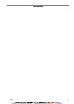
2. Install hose connections. Refer to label 71459929 on page 13.
(Dwg. 71459929)
Form MHD56401 Edition 3
13


