21
MAINTENANCE SECTION
2. If the Lower Arbor Bearing (29) is being installed, it
is necessary to note the identification marks on the
Lower Arbor Bearing. The side of the Bearing having
black stains or black hash marks on the side of the
inner and outer races is opposite the flush ground
side.
3. Using your hand, push the Lower Arbor Bearing,
flush ground side inward, into the recess at the ma-
chined end of the Angle Head.
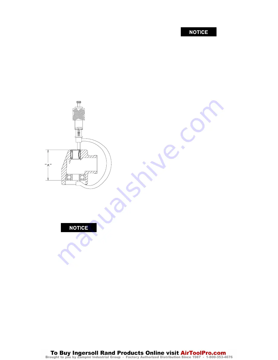
4. Using a 2” micrometer, take a measurement from the
inner ring of the Lower Arbor Bearing to the stamped
or closed end of the Upper Arbor Bearing.
See Dwg. TPD687.
(Dwg. TPD687)
Minimum
Dimension
“A”
in mm
1.36 34.65
Maximum
Dimension
“A”
in mm
1.38 35.00
5. Additional pressing of the Upper Arbor Bearing may
be required to finally attain the correct dimension as
indicated in the table above.
6. Remove the Lower Arbor Bearing.
In the following step, make certain any shims in-
cluded with the Lower Arbor Bearing are installed
onto the Arbor between the Bevel Gear (21) and
the Bearing.
7. Using a sleeve that contacts the inner ring of the Low-
er Arbor Bearing, press the Bearing, flush ground
side of the Bearing trailing onto the Arbor (31).
8. Slide the Bevel Gear, geared face trailing, onto the
small threaded end of the Arbor, aligning the integral
keys of the gear with the slotted keyways in the
Arbor.
*
Product of National Starch and Chemical Corporation.
** Product of N.D. Industries.
The Bevel Gear and Bevel Pinion are specially
matched sets.
Replace these parts only as a
matched set.
9. Thoroughly clean the small threads on the Arbor
above the Bevel Gear and the threads in the Bevel
Gear Nut (28).
10. Apply a thin coat of Permalock HM118* to the
threads of the Bevel Gear Nut and the Nut threads on
the Arbor. Thread the Bevel Gear Nut onto the Arbor
to retain the Bevel Gear and tighten the Nut to 10 to
12 ft–lb (13.5 to 16.2 Nm) torque. Grease the Bevel
Gear with 1.5 cc of Ingersoll–Rand No. 67 Grease.
11. Form the Wick (27) into a horseshoe shape and insert
it into the Angle Head. Push the Wick into the open-
ing until it is compressed approximately 0.030” below
the bevel gear bore. Soak the Wick with approximate-
ly 1.5 cc of Ingersoll–Rand No. 63 Oil. Do no substi-
tute any other oil.
12. Carefully grasp the assembled motor in leather– cov-
ered or copper–covered vise jaws with the Throttle
Lever downward.
13. Install the motor Clamp Nut (24), threaded end trail-
ing, onto the motor end of the Angle Head. Spread the
Clamp Spacer (23) and install it on the motor end of
the Angle Head against the Clamp Nut.
14. Position the output end of the Angle Head upward and
opposite with the Throttle Lever and thread the
Clamp Nut onto the Motor Housing. Using the Clamp
Nut Wrench (52), tighten the Nut to 20 to 25 ft–lb
(27 to 34 Nm) torque. This is a left–hand thread, turn
counterclockwise to tighten.
15. Insert the assembled Arbor into the Angle Head, bevel
gear end first, making sure the teeth on the Bevel
Gear and Pinion mesh. Rotate the Arbor manually to
determine that they are rotating smoothly.
16. Thoroughly clean the internal threads of the Angle
Head and the threads on the Arbor Bearing Cap (30).
17. Carefully apply a uniform coat of Vibra–Tite VC3
No. 205 ** to both sets of threads and allow the com-
pound to cure for 10 to 20 minutes.
18. Using the Arbor Bearing Cap Wrench (53), install the
Arbor Bearing Cap and tighten to 12 to 15 ft–lb (16.2
to 20.3 Nm) torque. The Bearing Cap has a left–hand
thread: turn counterclockwise to install.


