

3
ADJUSTMENTS
DO NOT SUBSTITUTE ANY OTHER FLUID.
Failure to use the impulse mechanism fluid provided
could damage the tool, increase maintenance and
decrease performance. Use only clean fluid in these
tools.
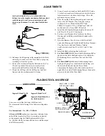
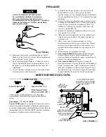
(Dwg. TPD1265)
10. Submerge the fill opening in the remainder of the fluid,
and using a wrench, rotate the Drive Shaft to purge any
remaining air from the system.
11. Remove the mechanism from the fluid and use the Tee
Wrench to push the Piston Stop Assembly slowly
downward until fluid flows from the fill opening.
12. Thread the Oil Plug with the Oil Plug Seal and Seal
Support into the mechanism until it is snug.
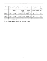
13. Using a 2 mm hex wrench on the Model 900P–EU and a
1.5 mm hex wrench on all other models, turn the Torque
Adjustment Screw clockwise until it stops. This is the
maximum torque position.
14. Wipe the outside of the mechanism dry and clean and
remove the Oil Chamber Plug. Using the syringe,
withdraw 0.35 cc of fluid from 500P–EU and
500PQ1–EU models, 0.50 cc of fluid from 700P–EU
models and 0.85 cc from 900P–EU models.
15. Install the Oil Chamber Plug and tighten it between 20
and 25 in–lb (2.3 and 2.8 Nm) torque.
16. Position a new Hammer Case Gasket on the Motor
Housing and install the assembled mechanism on the
rotor shaft.
17. Place the Hammer Case Cover over the Drive Shaft
against the Housing and Gasket. Install the three Hammer
Case Cap Screws and Lock Washers. Tighten
each Screw between 45 an 50 in–lb (5.1 and 5.6 Nm)
torque.
18. Install the Rubber Housing Boot on the tool.
19. For Model 500PQ1–EU, install the Bit Retaining Ball in
the hole in the Drive Shaft and capture it by sliding the
Bit Retaining Sleeve, small bore first, onto the Drive
Shaft.
20. For Model 500PQ1–EU, install the Retaining Sleeve
Spring and Spring Seat, counterbored end trailing, over
the drive shaft hub and into the Sleeve.While
compressing the Spring, with a thin blade screwdriver
against the Seat, install the Retaining Ring in the annular
groove in the hub of the Drive Shaft.
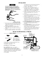
PLACING TOOL IN SERVICE
LUBRICATION
Ingersoll–Rand No. 50
Ingersoll–Rand No. 67
Ingersoll–Rand Fluid Part
No. EQ106S–400–1
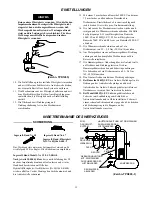
Always use an air line lubricator with these tools.
We recommend the following Filter–Lubricator–Regulator
Unit:
For International – No. C18–C3–FKG0
After each 20,000 cycles, or as experience indicates, drain
and refill the Impulse Unit Drive Assembly as instructed
in this manual using the Fluid Replacement Kit (Part
No. EQ106S–K400). Lubricate the hex drive and the output
shaft before assembly.
MAIN LINES 3 TIMES
AIR TOOL INLET SIZE
TO
AIR
SYSTEM
TO
AIR
TOOL
LUBRICATOR
REGULATOR
FILTER
BRANCH LINE 2 TIMES
AIR TOOL INLET SIZE
DRAIN REGULARLY
COMPRESSOR
(Dwg. TPD905–1)


