22
Figure 3.3
1
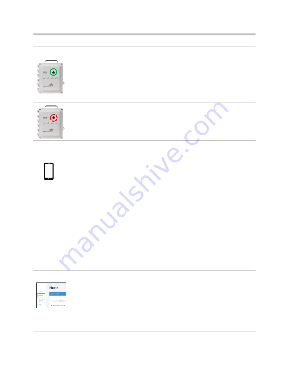
Power on the RGX
On the case lid, press the power button for approximately 5 seconds until the power-button light turns
on. Observe the power-button light and proceed as noted below.
Green only
(blinking or solid)
Continue.
Includes red
(blinking or solid)
See
Table 3.6 Power-button light indicators
before continuing
.
Light does not turn on
Try again. If the condition persists, the unit may not have
sufficient charge. Charge the unit before continuing.
2
Activate Wi-fi access mode
Tap the power button three times quickly. If the power-button light
blinks red
, continue; otherwise, try
again.
3
Log into the RGX Configuration Interface
Check the smart device for a list of detected wi-fi devices:
•
Locate the serial number for the unit; highlight it and click on it.
•
When prompted to enter a security key, enter 0 (zero) followed by the RGX’s
On the smart device, open a browser:
•
In the browser address bar enter https:// followed by the RGX IP address.
•
If the IP address is unknown, enter: 192.168.1.1
When prompted, enter the log-in credentials below to access the RGX Configuration Interface:
•
User name: RGXadmin (case sensitive)
•
Password: Unit
Note:
It is recommended that the password be changed after initial log in. The case-sensitive
password requirements follow.
Use a minimum of 8 characters in any order, including minimally, at least:
•
one number
•
one lowercase letter
•
one uppercase letter
•
one symbol from this set: () ` ~ ! @ # $ % ^ & * - + = | \ { } [ ] : ; " ' < > , . ? /
4
Configure options
Access
Settings
RGX Gateway only
•
Review the RGX
–
iNet communications options: cellular, wi-fi, and Ethernet. Enable or disable
each option.
•
For each enabled option, enter, select, or edit the required values.
Reminder:
If your company’s wireless
network uses
“WPA2
-
Enterprise”
security, the RGX
Interface will require the upload of a
certificate of authenticity
that is 2048-bit or less and
supplies the full chain of trust.
Summary of Contents for RGX Series
Page 22: ......
Page 26: ......
Page 48: ......
Page 58: ...48 Figure A 1 B External electrical connections in a nonhazardous location To Figure A 1 A ...
Page 59: ...49 Figure A 1 C Internal electrical connections ...
Page 60: ......


