background image


10 


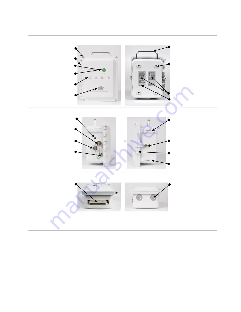
Case lid  

Case base  


Fastener (4x);  

1.69 N m; 240 oz in screw torque  


Handle 

Hinge  

Screw hole (4x); 

for use with 

optional Wall Mount kit or 
Magnet Mount kit


Power button  

Indicator light (system-power-

communication status)  

Indicator light quick 

reference

a


NFC target  

Labels 
MAC addresses 

(on label)


Side (left) 

Side (right) 


Indicator light  

(charging status) 


Serial number (S/N) 

Intrinsic safety (IS) power 

port and tethered cap 


Charging power supply port 

and tethered cap 

Vent 

Tether-chain screw 

Lock tabs 

(for use with 

customer-supplied item)


Activation code 


Top 

Bottom 


Handle 


Conduit-hub plug (2x); 

each 

covers a hole size of 27.8 mm 

(1.09 ″) 


Figure 1.2.A Hardware overview (exterior)


a

Depicts 

key

 connectivity and power light indicators. For a complete list of indicator light patterns and their meanings, see 

Table 3.6 Power-

button light indicators

. 


Summary of Contents for RGX Series

Page 1: ...Product Manual The Safety Team s Resource for Setup Installation Operation and Service Edition 5 November 1 2019 Part number 17158071 1 ...

Page 2: ...trial Scientific Corporation Pittsburgh PA USA Industrial Scientific Co Ltd Shanghai China 2018 2019 Industrial Scientific Corporation All rights reserved Published 2019 Revision 6 www indsci com rgxgateway ...

Page 3: ...atibilities 6 Instruments 6 Operational power sources 6 Specifications 7 RGX Gateway specifications 7 Battery specifications 9 Power supply accessory run time effects 9 Hardware Overview 9 Chapter 2 13 Deployment Planning 13 Introduction 13 Communications 13 RGX Gateway instrument communication LENS Wireless 13 RGX Gateway iNet communication 14 Wireless Settings and Connections 14 Chapter 3 17 Set...

Page 4: ...Operation 29 Introduction 29 Site Selection 31 Placement and Mounting 32 Installation Preparation 32 Installation 33 Operation Precheck 37 Chapter 5 39 Service and Warranty 39 Service 39 Supplies 39 Instructions 39 Warranty 46 Limitation of Liability 46 Appendix A 47 Requirements for electrical connections Industrial Scientific Control Drawing 1810D9509 200 47 Appendix B 51 Applicable Certificatio...

Page 5: ... the battery 19 Table 3 2 Configuration applications 20 Table 3 3 Supplies needed for configuration 21 Table 3 4 RGX Configuration Interface instruction sets by access method 21 Figure 3 3 Wi fi access method for RGX Configuration Interface 23 Figure 3 4 Ethernet access method for RGX Configuration Interface 25 Table 3 5 Internal indicator lights and their meanings 26 Figure 3 5 iNet settings 27 T...

Page 6: ...iv Figure A 1 B External electrical connections in a nonhazardous location 48 Figure A 1 C Internal electrical connections 49 ...

Page 7: ...e peut être présente WARNING The RGX Gateway offers these power input options 12 V Charger Port IS Power Port and 9 30 VDC Terminal Block When connecting external power select only a single power input type connecting multiple power inputs is not supported CAUTION RGX Gateway for use in hazardous locations only as to intrinsic safety per control drawing 1810D9509 200 AVERTISSEMENT RGX Gateway pour...

Page 8: ...y not cause interference and 2 this device must accept any interference including interference that may cause undesired operation of the device Le présent appareil est conforme aux CNR d Industrie Canada applicables aux appareils radio exempts de licence L exploitation est autorisée aux deux conditions suivantes 1 l appareil ne doit pas produire de brouillage et 2 l utilisateur de l appareil doit ...

Page 9: ...non dangereux seulement OU dans les zones classes suivantes zones dangereuses UNIQUEMENT Table 0 1 RGX Gateway hazardous location certifications Certifying Body Classificationa Approved temperature range c UL usb Class I Division 2 Groups A B C and D Temperature Code T6 Zone 2 Ex ic ec IICT6 Gc CA AEx ic ec IICT6 Gc US 20 C to 55 C 4 F to 131 F ATEXb Zone 2 Ex ic ec IICT6 Gc DEMKO 19 ATEX 2192X 20...

Page 10: ...rd Frequency Output 2402 MHz to 2480 MHz Maximum Power 9 9 dBm 9 7 mW Antenna Gain 0 0 dBi Bluetooth Low Energy Radio Transceiver Module Frequency Output 2405 MHz to 2480 MHz Maximum Power 4 dBm 2 5 mW Antenna Gain 0 5dBi Wi fi Radio Transceiver Module Supported Channels Frequencies 1 thru 13 2412 MHz to 2472 MHz Maximum TX Power 17 0 dBm 50 1 mW 1 DSSS 13 5 dBm 22 3 mW 54 OFDM Antenna Gain 1 9 dB...

Page 11: ...reless group Linked Equipment Network for Safety System Overview LENS Wireless is a long range power efficient wireless mesh network from Industrial Scientific The exchange of LENS group data supports the live monitoring capabilities of iNet Now From a computer or smart device iNet Now users can learn on a live basis about everything from instrument gas readings to gas alarms man down events panic...

Page 12: ... 1 A System overview iNet Main facility RGX Gateway iNet Now users live monitoring real time alerts RGX Gateway in LENS repeater mode extending the facility s LENS Wireless group to another building RGX in LENS repeater mode Out building Figure 1 1 B System overview with RGX in LENS repeater mode ...

Page 13: ...an host up to 25 equipment items More than one RGX can be included in a LENS group RGX units operating in LENS repeater mode also use this network Instrument data exchanged through LENS are automatically encrypted with the Industrial Scientific key Optionally a customer supplied encryption key may be used RGX Gateway iNet The RGX can send data it receives from gas detection instruments to iNet The...

Page 14: ...he RGX iNet data exchanges are automatically encrypted using industry standard Transport Layer Security TLS 1 2 Note RGX Gateway iNet communication does not apply to RGX units operating in LENS repeater mode Location The RGX Gateway is suitable for indoor or outdoor use in locations that meet the product s certified uses and specifications Indoor operation is suitable only when a unit s GPS locati...

Page 15: ...nent installations The RGX can receive operational power from a compatible power supply accessory only from Industrial Scientific use of each accessory requires the RGX to be equipped with its Intrinsic Safety IS Cable Adapter This option is well suited for use conditions that do not require permanent installation but demand a run time exceeding that of the factory installed battery In a nonhazard...

Page 16: ...talled battery can be extended with the use of a compatible power supply accessory only from Industrial Scientific Each power supply accessory as listed below has unique use restrictions or certified uses Before using either accessory read and understand its product manual and control drawing 1810D9509 200 as represented by the schematic diagrams in Appendix A of this manual These schematics are a...

Page 17: ... the dedicated ports on the RGX terminal block Before connecting power read and understand control drawing 1810D9509 200 as represented by the schematic diagrams in Appendix A of this manual The charging power supply and power cord part number 17158665 can be used to provide operational power to the unit only when the unit is operated in a nonhazardous location Specifications RGX Gateway specifica...

Page 18: ...rns indicate operational status Indicator light on side panel indicates battery charging status Internal buttons and indicators Buttons One SW1 RESET resets the unit to its original factory setting values Status indicators Four COMM indicates communication status LENS indicates LENS Wireless status ERR2 indicates communication error ERR1 indicates system error Ethernet indicators Two Yellow indica...

Page 19: ...utes of alarm data every 24 hours and is set to upload noncritical data every five minutes bWhen charged at room temperature 25 C 73 F cBattery charging is suspended in temperatures below 5 C 41 F and above 45 C 113 F Power supply accessory run time effects The RGX Gateway can draw operational power from compatible power supply accessories only from Industrial Scientific The RGX can run indefinite...

Page 20: ...Indicator light charging status Serial number S N Intrinsic safety IS power port and tethered cap Charging power supply port and tethered cap Vent Tether chain screw Lock tabs for use with customer supplied item Activation code Top Bottom Handle Conduit hub plug 2x each covers a hole size of 27 8 mm 1 09 Figure 1 2 A Hardware overview exterior aDepicts key connectivity and power light indicators F...

Page 21: ...PWR IN 9V 30V 9 30 VDC with 5 0A maximum current Figure 1 2 B Hardware overview interior aWhen the factory reset button is pressed and held for approximately 20 seconds the unit s settings will revert to the original factory setting values After a reset adjust unit settings as needed bFor use with customer supplied customer installed fixed DC power that supplies a compatible input voltage range of...

Page 22: ......

Page 23: ...ode RGX units operating in this mode only communicate using this network The other network allows the RGX to send instrument data to iNet which supports the live monitoring capabilities of iNet Now Both networks are described below RGX Gateway instrument communication LENS Wireless The RGX can communicate with gas detection instruments only when the equipment items are set to operate in the same n...

Page 24: ...emized in Table 2 1 are required for iNet Now live monitoring of LENS group peers Table 2 1 Required equipment settings for iNet Now live monitoring Equipment items Setting item RGX Gatewaya Ventis Pro Radius BZ1 LENS Wireless No setting required Menu Wireless Setting LENS Wireless Value iNet Now and Local Menu Wireless Setting Wireless Radio Value iNet Now and Local LENS Wireless Groupb Menu LENS...

Page 25: ...enerally maintained when no interference is present by keeping the equipment items within their range guidelines see Table 2 2 below Provided the required LENS Wireless connections are maintained the live monitoring of equipment items accommodates worker and equipment movement Table 2 2 Range guidelines to maintain LENS Wireless connections Line of sight distance maximum LENS Power Mode Setting Eq...

Page 26: ......

Page 27: ...unpacking process account for and examine each ordered item If any item is missing or appears to have been damaged contact Industrial Scientific or an authorized distributor of Industrial Scientific products After unpacking peel the protective plastic film from the case lid Table 3 1 Package contents Quantity Item Description As ordered As ordered RGX Gateway or RGX Gateway operating in LENS repea...

Page 28: ...he unit s Serial Number and Activation Code Use the OK button to submit the information Note When an RGX has not yet been activated or when deactivated the power button light will slowly blink red See Table 3 6 Power button light indicators for more information In this state the RGX cannot connect to iNet to relay instrument events Gas detection instruments To transmit gas detection instrument dat...

Page 29: ...or a full stop connection feedback is felt Plug the power cord into a compatible outlet Check the unit s charging status indicator light The green light will first blink on and off to indicate a precharging state The green light will stay on but stop blinking to indicate charging is in progress The light will turn off to indicate the battery is fully charged When the battery is fully charged unplu...

Page 30: ...n requires the use of one or two apps the RGX Configuration Interface Interface and iNet software Generally as outlined below the Interface is used to configure RGX to iNet communication settings iNet software is used for all other RGX settings see below After initial configuration use each app as needed to edit the settings it supports Table 3 2 Configuration applications App RGX Configuration In...

Page 31: ...s WPA2 Enterprise security the RGX Interface will require the upload of a certificate of authenticity that is 2048 bit or less and supplies the full chain of trust As with most applications the Interface is subject to timing out when idle When a data field appears in gray no entry is required Within each section work from top to bottom When a test button appears use it after entering all the requi...

Page 32: ...he RGX s activation code On the smart device open a browser In the browser address bar enter https followed by the RGX IP address If the IP address is unknown enter 192 168 1 1 When prompted enter the log in credentials below to access the RGX Configuration Interface User name RGXadmin case sensitive Password Unit activation code Note It is recommended that the password be changed after initial lo...

Page 33: ...Figure 3 3 Wi fi access method for RGX Configuration Interface Figure 3 4 1 Shut down the RGX Set the unit on the work surface case lid facing up Observe the power button light If the light is off continue If the light is on and green only blinking or solid shut down the unit Press the power button for approximately 7 seconds when its light starts blinking release the button The power button light...

Page 34: ...have sufficient charge Charge the unit before continuing 4 Observe interior LEDs Observe the interior LEDs located near the left edge of the PCB printed circuit board From top to bottom they are labeled COMM STAT LENS STAT ERR2 and ERR1 Each light may be on or off Check the ERR2 light third from top At this point it may be red continue Note If operating on battery power only the interior LEDs will...

Page 35: ... them to the operational status column in Table 3 5 below The LENS Wireless status light will be off until another equipment item joins the LENS group otherwise if there are no errors or connection issues disconnect the Ethernet cable from the unit If there are errors or issues recheck the work completed to this point If an issue persists contact Industrial Scientific Disconnect the cable from the...

Page 36: ...ment items are in the LENS group ERR2 Communication status Red There is a communications error Off There is no communications error ERR1 System status Red There is a system error Off There is no system error Ethernet cable port Left LED Ethernet connection status Green There is no Ethernet connection Off There is an Ethernet connection Right LED Ethernet connection speed Yellow The Ethernet connec...

Page 37: ...e name can be edited under Sites aWhen setting intervals consider the application For example while a longer interval for sending the unit s GPS data uses less battery power a shorter interval may be better suited if the unit is to be frequently moved among sites bAn RGX Gateway set for always on operation cannot be manually shut down and will ignore manual shutdown attempts until this mode is dea...

Page 38: ...e unit is communicating with iNet but its GPS is not working or The unit cannot communicate with iNet RGX is set to LENS repeater mode Both green and red Alternating Low battery warning or The power button has been pressed and the unit is shutting down Red only Solid not blinking The unit is not operational because there is no power Rapid blinking Indicates that wi fi access mode has been activate...

Page 39: ...or uninstall mount or otherwise secure or remove the unit must comply with and be used in ways that meet any restrictions imposed by the hazardous classified area local state or national codes regulations standards permits or other requirements and the Authority Having Jurisdiction AHJ The wiring of intrinsically safe circuits follows these examples NFPA 70 National Electric Code NEC Article 504 C...

Page 40: ...imum current of 5 0A Hubs and conduits suitable for the application and hole size 27 8 mm 1 09 ISERTPSb from Industrial Scientific Operational power suitable for extended run time installations Before using the ISERTPS ensure your application meets the product s certified uses and restrictions read and understand the ISERTPS Product Manual part number 17158248 ERTPSb from Industrial Scientific Ope...

Page 41: ...rdance with the instructions provided in the respective product manual If an ISERTPS or ERTPS power supply accessory will be used maintain a minimum distance of 5 m 16 4 between the RGX and the accessory or any nearby ISERTPS or ERTPS accessories see Figure 4 1 below This allows the RGX to operate in a manner designed to prevent radio frequency interference per FCC Federal Communications Commissio...

Page 42: ...ional Magnet Mount Kit is used to mount the unit to a metal surface IMPORTANT Do not use the Magnet Mount Kit with units that draw operational power from a fixed DC power source Installation Preparation Based on how the RGX will be mounted or placed and its intended operational power source and communications options use the information below to determine which preparation tasks are needed Refer t...

Page 43: ...6 Zone 2 AEx ic ec IICT6 Gc Ambient Temperature 20 C to 55 C Note For a list of applicable hazardous location certifications see Table 0 1 RGX Gateway hazardous location certifications WARNING The RGX offers these power input options 12 V Charger Port IS Power Port and 9 30 VDC Terminal Block When connecting external power select only a single power input type connecting multiple power inputs is n...

Page 44: ...ll stop connection feedback is felt a No external power source If the RGX will draw operational power only from its factory installed battery cap the charging power supply port and the IS power port Skip to Operation Precheck b Power supply accessory ISERTPS or ERTPS IMPORTANT The warning above also applies to this option If the RGX will draw operational power from a compatible power supply access...

Page 45: ...and includes red light blinking or solid see Table 3 6 Power button light indicators before continuing Note An RGX Gateway set for always on operation cannot be manually shut down and will ignore manual shutdown attempts until this mode is deactivated via iNet 3 Port check Cap each power port that will not be used for operational power charging power port and IS power port shown here When installi...

Page 46: ...w a or b to select an external power input for the RGX and follow that set of instructions WARNING The RGX offers these power input options 12 V Charger Port IS Power Port and 9 30 VDC Terminal Block When connecting external power select only a single power input type connecting multiple power inputs is not supported a Power supply accessory ISERTPS or ERTPS IMPORTANT The warning above also applie...

Page 47: ...e strain relief on the Ethernet cable resists full closure of the unit use a 90 adapter or short adapter cable Close the case lid from left to right Using a T25 torx screwdriver reinstall the four fasteners that secure the case lid to the case base Tighten them to a torque value of 1 69 N m 240 oz in Figure 4 3 Installation that includes an external power source Ethernet or both Operation Precheck...

Page 48: ......

Page 49: ...m is highly flammable o Use protective gloves and eyewear to avoid a potentially severe pinch injury cut or splinter Service tasks that can be completed by Industrial Scientific customers are described in this manual Table 5 1 indicates which parts and components are customer replaceable All other service tasks should be performed only by Industrial Scientific or its authorized service centers Sup...

Page 50: ...t 3 IS power port cap 18109571 Includes tether chain screw sealing gasket washers and hex nut 4 Tether chain screw Screw torque 0 63 Nm 90 oz in 5 Vent 18109572 Vent nut torque 1 27 Nm 180 oz in 6 Conduit hub plug 18109574 Screw torque 1 27 Nm 180 oz in Accessories Wall Mount Kit 17157620 Screw torque 1 13 to 1 69 Nm 160 to 240 oz in Magnet Mount Kit 18109564 Do not use with a unit that will draw ...

Page 51: ...information printed on the back of the RGX Locate the unit s LAN MAC and WAN MAC values printed on the factory affixed label on the back of the unit Record these two values onto the kit label in the areas provided Affix the kit label to an area of the RGX that will be visible during operation Magnet Mount Kit installation Do not use with a unit that will draw power from a DC fixed power source Ins...

Page 52: ... adapter connector to the wide notch on the IS port push on to the port to connect Turn the swivel connector clockwise approximately 45 until it clicks closed or a full stop connection impact is felt Connect the other end of the adapter in accordance with the Product Manual instructions from the compatible Industrial Scientific power supply accessory that will be used Figure 5 2 Mounting kit and I...

Page 53: ...l and installation Conduit hub plug removal Do not reinstall any used conduit hub plug components once removed a plug s seal is compromised and other plug components may become altered or damaged Locate the conduit hub plugs at the bottom of the case base Inside the case hold the nut in place with a 3 8 open end wrench and turn the T20 torx screw counterclockwise to loosen Remove the nut two inter...

Page 54: ...T20 Torx screw Remove the protective paper to expose the adhesive side of the gasket Inside the case center and place the gasket over the conduit hub plug opening on the base From outside of the case place the torx screw into the concave side of the washer and place over the base opening Inside the case place the next washer convex side down over the screw and fixed gasket Follow with the sealing ...

Page 55: ...copper ground shield to remove the second flat washer and sealing gasket Turn the port cap counterclockwise approximately 45 separate from the port Discard the removed items according to company policy Port cap installation Hex nut Flat washer Copper ground shield Flat washer Sealing gasket Connect the replacement port cap to the appropriate port IS port or Charging port turn clockwise approximate...

Page 56: ...USE OF ANY PRODUCTS SOLD HEREUNDER WHETHER SUCH CLAIM IS PLEADED IN CONTRACT OR IN TORT INCLUDING STRICT LIABILITY IN TORT AND WHETHER INDUSTRIAL SCIENTIFIC HAS BEEN ADVISED OF THE POTENTIAL FOR SUCH DAMAGES Industrial Scientific s total liability hereunder from any cause whatsoever except liability from personal injury caused by Industrial Scientific s negligence whether arising under contract wa...

Page 57: ...47 Appendix A Requirements for electrical connections Industrial Scientific Control Drawing 1810D9509 200 Figure A 1 A External electrical connections in a hazardous location From Figure A 1 B ...

Page 58: ...48 Figure A 1 B External electrical connections in a nonhazardous location To Figure A 1 A ...

Page 59: ...49 Figure A 1 C Internal electrical connections ...

Page 60: ......

Page 61: ...ol Equipment 1st Ed UL 2054 Standard for Household and Commercial Batteries 2011 09 14 IEC 60079 0 2017 Explosive atmospheres Part 0 Equipment General requirements IEC 60079 7 2017 Explosive atmospheres Part 7 Equipment protection by increased safety e IEC 60079 11 2011 Explosive atmospheres Part 11 Equipment protection by intrinsic safety i EN 60079 0 2018 Explosive atmospheres Part 0 Equipment G...

Page 62: ... 86 400 820 2515 To locate a nearby distributor of our products or an Industrial Scientific service center or business office visit us at www indsci com Rendez vous sur notre site Web www indsci com si vous voulez trouver un distributeur de nos produits près de chez vous ou si vous recherchez un centre de service ou un bureau Industrial Scientific Besuchen Sie uns unter www indsci com um einen Ver...

Reviews: