21
STNM ed 07/07
NIKE Mini Export
Technical Documentation
Technical Documentation
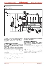
The electrical circuit of the NIKE Mini 24-28-24 S boiler is
controlled 100% by a p.c.b. which controls boiler functions.
Some of the control and safety devices work at mains voltage
(230 Vac)
while others at low voltage.
Electrical circuit.
230 V AC circuit.
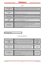
Control and safety devices.
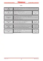
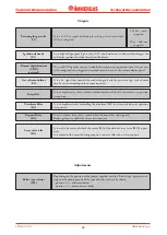
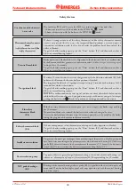
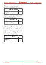
It detects burner ignition, being hit by its flame.
It is connected to the integrated board.
Detection electrode
(E2)
They interrupt power to the circuit when power input is over
3.15 A.
They are mounted on the integrated board.
Line fuse (F1)
Neutral fuse (F2)
3.15 AF 250 V
fuse
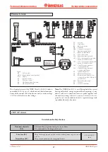
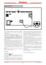
Legend:
B1 - Delivery probe
CRD - Remote digital control (optional)
DS1 - Display
E1 - Ignition electrode
E2 - Detection electrode
E4 - Overheating safety thermostat
E6 - Flue safety thermostat
F1 - Line fuse
F2 - Neutral fuse
JP1 - Boiler type selector
M1 - Circulator
M30 - 3-way valve (motorised)
S2 - Functioning push button
S3 - Block reset push button
S4 - D.h.w. flow switch
S20 - Room thermostat (optional)
S21 - D.h.w. temperature increase push
button (if enabled to work)
S22 - D.h.w. temperature reduction push
button (if enabled to work)
S23 - Central heating temperature
increase push button
S24 - Central heating temperature
reduction push button
T1 - Ignition transformer
T2 - Boiler board transformer
U1 - Rectifier located inside the con-
nector of the gas valve (Honeywell
gas valve only)
X40 - Room thermostat jumper
Y1 - Gas valve
Y2 - Gas valve modulator
Nota:
The NIKE Mini 24 S is a wall-hung boiler for central
heating only which, using an optional kit comprising a 3-way
electric valve and a domestic hot water probe together with
the necessary wiring
(that can be connected directly to the inte-
grated board)
, can be combined with a separate storage tank
to produce domestic hot water.
���������������
����������������
�����������������
�������������������
��������������
������
�������
�����
�����������


