17
STNM ed 07/07
NIKE Mini Export
Technical Documentation
Technical Documentation
1
1
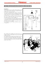
Primary
circuit
delivery
Primary
circuit
return
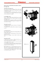
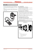
D.h.w. flow switch (2).
Whenever domestic hot water is drawn at a rate of at least 1.5
l/min and a dynamic pressure of 0.3 bar, the flow switch (2)
enables the boiler to work in the d.h.w. mode.
This is done by means of a magnet that, lifting when hit by the
flow of domestic cold water, moves near to an electrical contact
(reed relay)
causing it to move thanks to the magnetic effect.
When the contact closes, which is located outside the pipe
through which the water flows, it enables the adjustment board
to start the domestic hot water priority phase.
It consists of two parts
(one in brass and one in plastic)
that are
coupled together and locked with a pin.
A G1/4” thread on its body connects it to the filling unit
(3).
An 7.1 l/min
(2 bar)
for model 24 and a 9.2 l/min
(2 bar)
flow
limiter (1) for model 28 is installed at the flow switch exit.
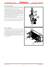
D.h.w. exchanger.
It is a water-water exchanger made of stainless steel plates one
on top of the other - 12
(for model 24)
and 14
(for model 28)
- on whose surface the boiler circuit water and the domestic
cold water flow in counter current and through which the heat
exchange takes place between the two lots of water.
The hydraulic coupling is done using four O rings (1) so it
can be connected directly to the d.h.w. inlet body and to the
d.h.w. outlet body.
D.h.w.
outlet
Cold
water
inlet
Cold
water inlet
1
2
3


