


32
English
5.4 Dynamic-range processing of a signal
Specific signal compressors are available for all input channels, sub-
groups and Aux ways as well as for the internal effect ways and the
sum channel MAIN� In addition, all input channels and the two internal
effect ways feature noise gates�
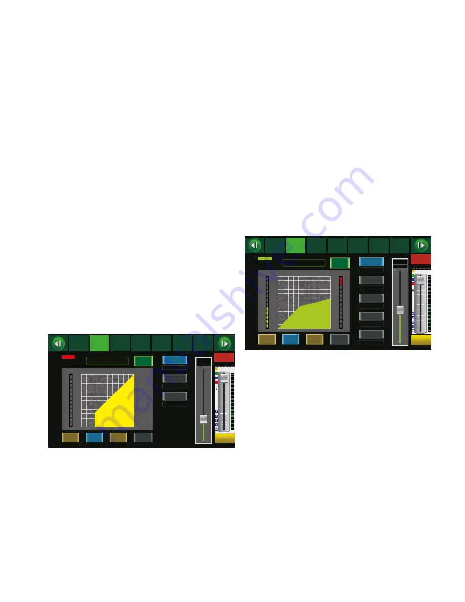
5.4.1 Noise gate
A signal can only pass a noise gate when the signal level exceeds an
adjustable threshold value� This can, for example, be used to suppress
the noise floor of a signal source or the crosstalk of other instruments
when sound is picked up with microphones�
1) With the input channel or with effect channel FX 1 or FX 2 select-
ed, press the key GATE /COMP (22)� The screen view of the noise
gate will be displayed (fig� 12)� If the compressor view is displayed
instead (fig� 13), press the key again�
2) Tap the button OFF to switch the noise gate on� The lettering of
the button will change to ON and the button will be highlighted
in colour�
3) Use the keys
,
,
,
(18) or tap the appropriate button on the
screen to select the parameters to be adjusted�
– Threshold
threshold value; the noise gate will open when the
signal level has exceeded this value
– Attack
attack time
– Release
time after which the noise gate will close when the
signal level has fallen below the threshold value
again
4) Use the rotary knob PARAMETER ADJUST (18) to change the value
of the parameter selected�
5) To switch off the noise gate, tap the button ON again�
The colour of the rectangle located above the word “Gate” indicates
the operating mode of the noise gate:
Grey: switched off
Red:
gate closed
Green: gate open
Level
(dB)
6
-8
-21
-28
-35
-42
-50
-56
-64
-71
-78
-84
CLIP
10
7
4
2
0
-2
-4
-7
-10
-20
-30
Release
Attack
45ms
350ms
-62dB
Save
Threshold
Copy
Load
Assign
Channel
System
Routing
PEQ
GEQ
FX 1
FX 2
Gate
Comp
Gate
Mixer
DCA
ON
Select
Channel
CH08
9dB
CH08
Long
Faders
Parameter
Mute
Solo
Default
-62dB
Thres.
Fig. 12 Noise gate
5.4.2 Compressor
The compressor attenuates the level above an adjustable threshold to
reduce the dynamic range of the signal� Thus, level differences (e� g�
due to varying distances between the singer and the microphone) or
signal peaks can be attenuated in order to improve gain setting options
and consequently to obtain a higher average volume�
The compressor may also be used as a level limiter: With a com-
pression ratio set to the maximum value (Comp Ratio = Limit), the
threshold value will define the level not to be exceeded (e� g� in the
sum channel MAIN to protect the amplification system connected
against overload)�
1) With the sum channel AUX, SUB or MAIN selected, press the key
GATE/COMP (22) once; with an input channel or with effect channel
FX1 or FX2 selected, press the key twice: the screen view of the
compressor (fig� 13) will be displayed�
2) Tap the button OFF to switch the compressor on� The lettering of
the button will change to ON and the button will be highlighted
in colour�
3) Use the keys
,
,
,
(18) or tap the appropriate button on the
screen to select the parameters to be adjusted�
– Threshold
threshold value; the gain will be attenuated when
the gain has exceeded this value
– Attack
attack time
– Release
time the gain takes to reach its original value after
the signal level has fallen below the threshold value
– Comp Ratio
compression ratio (1:1 = no compression,
10 :1 = high compression, Limit = level limitation)
– Comp Gain gain to balance the volume loss caused by the
compression
4) Use the rotary knob PARAMETER ADJUST (18) to change the value
of the parameter selected�
5) To switch off the compressor, tap the button ON again�
The colour of the rectangle located above the word “Comp” indicates
the operating mode of the compressor:
Grey: switched off or inactive
Green: compression active
Level
LIMIT
(dB)
16
12
7
3
-1
-5
(dB)
4
8
13
17
21
25
30
34
38
42
-10
-14
-18
-22
-26
-30
46
50
CLIP
10
7
4
2
0
-2
-4
-7
-10
-20
-30
Comp Gain
Release
Comp Ratio
Attack
70ms
350ms
4.5:1
0.0dB
-8dB
Save
Threshold
Copy
Load
Assign
Channel
System
Routing
PEQ
GEQ
FX 1
FX 2
Gate
Comp
Comp
Mixer
DCA
ON
Select
Channel
CH08
9.0dB
CH08
Long
Faders
Parameter
Mute
Solo
Default
-8dB
Thres.
Fig. 13 Compressor
5.5 Adjusting the sound of a signal
An adjustable high-pass filter, an adjustable low-pass filter and four
parametric filters are available for each input channel, subgroup and
Aux way as well as for each internal effect way and the sum channel
MAIN� In addition, all Aux ways and subgroups as well as the sum
channel MAIN feature graphic equalizers with 31 frequency bands�
5.5.1 Parametric equalizer
The parametric equalizer of a channel consists of a high-pass filter,
a low-pass filter and four parametric filters� The high-pass filter and
the low-pass filter offer selectable characteristics (Bessel, Butterworth,
Linkwitz-Riley) with different slopes (6 – 48 dB/ octave) as well as an
adjustable cut-off frequency� The other four filters provide the char-
acteristics Bell, High Shelf and Low Shelf� For each of these charac-
teristics, the filter frequency and the level of gain/attenuation can be
adjusted� In addition, the quality factor can be selected for the Bell
characteristic� Thus, with a high quality factor and substantial atten-
uation, it is possible to define a notch filter for narrow-band filtering
of disturbing frequencies�
1) With the input channel or sum channel selected, press the key
PEQ/GEQ (22)� The screen view of the parametric equalizer (fig�
14) will be displayed�
2) Tap the button OFF to switch on the equalizer� The lettering of
the button will change to ON and the button will be highlighted
in colour�


