IMG STAGE LINE DMIX-20 Instruction Manual Download Page 28

28

English

5  Operation

Switch on the mixer with the POWER switch (32)� The settings of the 
most recent operation will be loaded� Then the mixer will be ready to 
use and the screen (9) will display the view that has been selected in 
the system settings (

 chapter 6�2�2)� 

The steps described in the following merely serve as an aid; other 
procedures are possible�

5.1 Matching the input signal

To prevent the input channels from being overloaded and to achieve a 
perfect signal-to-noise ratio, first match the input gain of all used chan-
nels to the input signal� If a microphone connected or another signal 
source requires phantom power supply, please refer to chapter 5�1�1�
1)  Press one of the keys for the input channels (8) to select the chan-

nel� The key will light up�
There is no key to directly select the stereo input channel USB for 
digital audio signals from a computer� To select this channel: First 
use the key MIXER (22) to go to the screen view “Mixer” (fig� 20) 
or “Long Faders” (fig� 21) and then select the channel with the 
keys 

,

,

,

 (18) or by tapping the corresponding control on 

the screen�

2)  To switch off the indication for the Solo function: When the key 

SOLO METER (5) is illuminated, press the key so that it extinguishes� 
The level indicators (3) will now apply to the signal at the selected 
input�

3)  For perfect level control, use the control GAIN (1) of the channel 

selected to adjust the gain in such a way that the level on the 
indicator is approx� 0 dB� The CLIP LEDs must never light up for 
signal peaks; the signal will be distorted when the input channel 
is overloaded�
The stereo input channels (CH 17/18, CH 19/ 20 and USB) do not 
have any GAIN control; therefore, the input signal for these chan-
nels must be matched via the output level of the signal source�  
[The two controls (2) are used to directly adjust the channel volume 
of the channels CH 17/18 and CH 19/20 respectively�]
The LED indicator CLIP/ SIG next to the GAIN controls is an additional 
aid for checking the input signal: It will light up in green when 
a signal is available, and it will light up in red when the input is 
overloaded�

5.1.1  Phantom power

For microphones and other signal sources that require phantom power 
supply, a separate 48 V phantom power can be activated for each 
XLR connection of the input jacks MIC / LINE (27)�

CAUTION

Phantom power may damage signal sources with un-
balanced signal outputs� Never apply phantom power 
to any inputs to which units with unbalanced output 
are connected via XLR plugs�

When the phantom power is switched on or off or when a micro-
phone is connected with the phantom power switched on, signal 
peaks occur that, when amplified and sent to the outputs, may 
damage the speakers or your hearing� Therefore, first mute the cor-
responding channel with the key MUTE (23) (

 chapter 5�3�5) and 

use the controls HP1, HP2 and CTRL ROOM (15) to turn back the 
volume for the headphones and the control room to the left stop�

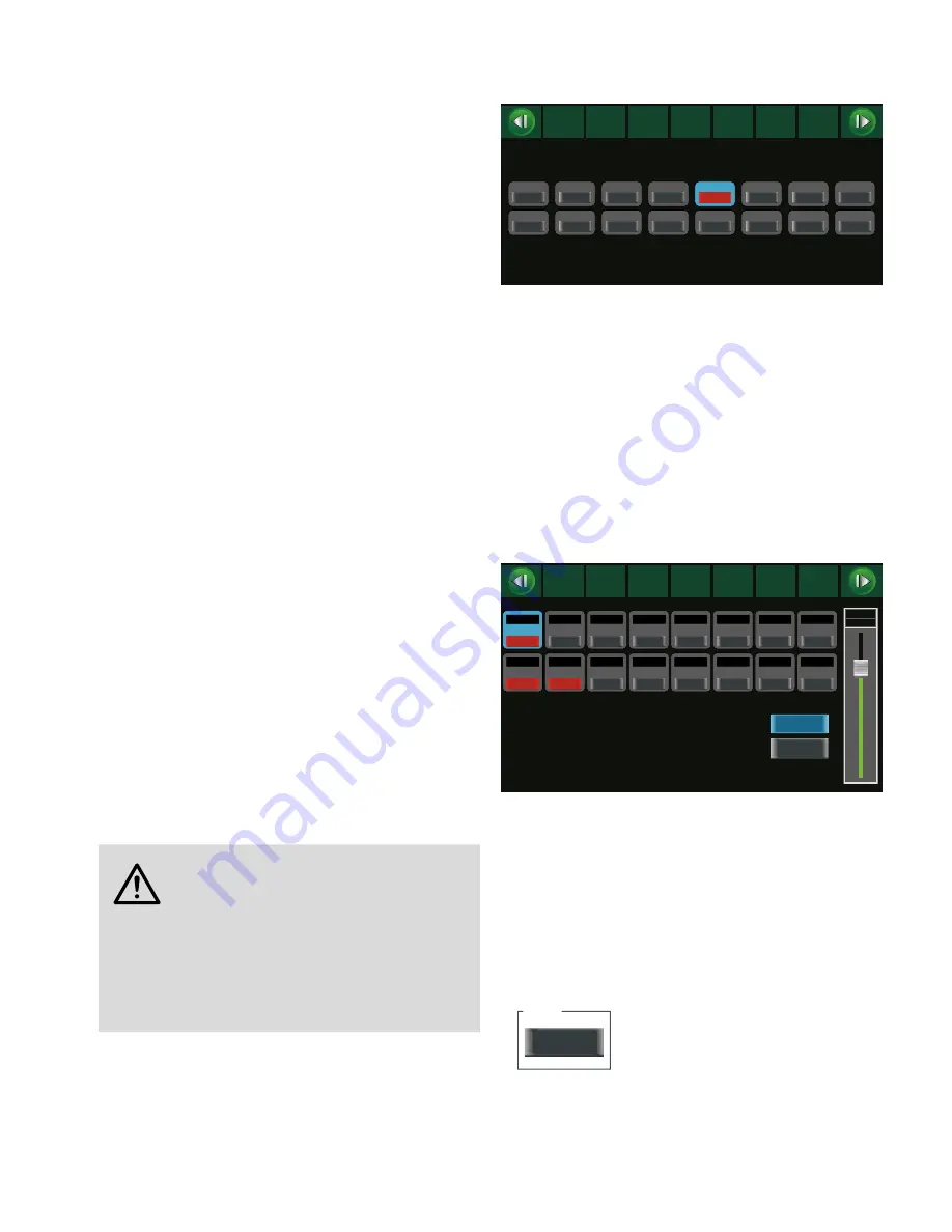
1)  Press the key 48 V (22)� The screen view for phantom power supply 

(fig� 4) will be displayed� The input channels for which phantom 
power has been activated will be indicated by a red button with 
the lettering ON� 

2)  To switch the phantom power on or off, tap the button of the 

desired input channel on the screen�

3)  When the phantom power is switched on, a confirmation prompt 

will be displayed: Tap “Yes” or press the key ENTER (20) to confirm�

4)  To exit this screen view, select a different view�

CH01

CH08

CH02

CH03

CH04

CH05

CH06

CH07

CH09

CH16

CH10

CH11

CH12

CH13

CH14

CH15

OFF

Assign

Channel

System

Routing

PEQ
GEQ

FX 1
FX 2

Gate

Comp

Mixer

DCA

Long

Faders

DC48V

OFF

OFF

OFF

ON

OFF

OFF

OFF

OFF

OFF

OFF

OFF

OFF

OFF

OFF

OFF

Fig. 4  Phantom power supply

5.1.2  Digital inputs

When the extension module for digital inputs and digital outputs is 
installed (

 chapter 4�4), an additional digital input signal will be 

available for each input channel�
1)  Use the key DIGITAL (22) to call up the screen view “Digital Input” 

(fig� 5) (press the key twice, if required)�

2)  Tap the appropriate area of the screen view to switch the digital 

signal for the respective input channel ON or OFF�

3)  When a channel has been selected (area highlighted in blue), use 

the rotary knob PARAMETER ADJUST (18) to adjust the gain for 
the digital signal�

When no extension module is installed, “Please insert the optional 
digital card!” will be displayed�

CH01

0.0dB

CH09

0.0dB

CH10

0.0dB

CH16

0.0dB

CH11

0.0dB

CH12

0.0dB

CH13

0.0dB

CH14

0.0dB

CH15

0.0dB

CH02

0.0dB

CH03

0.0dB

CH04

0.0dB

CH05

0.0dB

CH06

0.0dB

CH07

0.0dB

CH08

0.0dB

Assign

Channel

System

Routing

PEQ
GEQ

FX 1
FX 2

Gate

Comp

OFF

Mixer

DCA

Long

Faders

Parameter

CH01

0.0dB

OFF

OFF

OFF

OFF

OFF

OFF

OFF

OFF

OFF

OFF

OFF

OFF

OFF

OFF

OFF

Digital Output

Digital Input

Plesae insert the optional digital card !

ON

ON

ON

Fig. 5  Digital input

5.1.3  Signal inversion

The polarity of the signal can be inverted, if required� This is useful 
when, for example, an audio source is picked up with two microphones 
facing opposite directions (e� g� a drum whose sound is picked up from 
above and below)� In this case, one of the two microphone signals 
should be inverted to avoid phase cancellation while the two signals 
are being mixed�
1)  Use the key ASSIGN (22) to call up the screen view “Channel” 

(fig� 16) (press the key twice, if required)� The following button 
will be shown in the upper left:

Polarity

INV.

Fig. 6   

Alternatively, use the button “INV�” in the screen view “Assign” 
(fig� 9)�

2)  To invert the signal, tap the button; it will appear in colour� To 

deactivate the inversion, tap the button again�

Summary of Contents for DMIX-20

Page 1: ...CTRONICS FOR SPECIALISTS ELECTRONICS FOR SPECIALISTS ELECTRONICS FOR SPECIALISTS BEDIENUNGSANLEITUNG INSTRUCTION MANUAL MANUAL DE INSTRUCCIONES Digitales Audiomischpult Digital Audio Mixer DMIX 20 Bes...

Page 2: ...Gate 14 5 4 2 Kompressor 14 5 5 Klangbearbeitung eines Signals 14 5 5 1 Parametrischer Equalizer 14 5 5 2 Grafischer Equalizer 15 5 6 bersicht der Signalbearbeitung 15 5 6 1 Kanaleigenschaften kopier...

Page 3: ...al 32 5 4 1 Noise gate 32 5 4 2 Compressor 32 5 5 Adjusting the sound of a signal 32 5 5 1 Parametric equalizer 32 5 5 2 Graphic equalizer 33 5 6 Overview of the signal processing 33 5 6 1 Copying cha...

Page 4: ...e gate 50 5 4 2 Compresor 50 5 5 Ajustar el sonido de una se al 50 5 5 1 Ecualizador param trico 50 5 5 2 Ecualizador gr fico 51 5 6 Esquema del procesamiento de se al 51 5 6 1 Copiar las caracter sti...

Page 5: ...ELECTRONICS FOR SPECIALISTS ELECTRONICS FOR SPECIALISTS ELECTRONICS FOR SPECIALISTS ELECTRONICS FOR SPECIALISTS 5...

Page 6: ...instellung der Taste PFL 17 ob der Pegel vor der Pegeleinstellung des Kanals Taste leuchtet oder nach der Pegeleinstellung Taste leuchtet nicht angezeigt wird Ist kein Kanal als Solo gew hlt die Taste...

Page 7: ...sicht umgeschaltet werden GATE COMP Einstellungen der Dynamikprozessoren Noise Gate Kom pressor f r den gew hlten Kanal Bei den Eingangskan len und den Effektwegen FX1 2 kann bei wiederholtem Dr cken...

Page 8: ...40 C Stellen Sie keine mit Fl ssigkeit gef llten Gef e z B Trinkgl ser auf das Ger t Die im Ger t entstehende W rme muss durch Luftzirkulation abge geben werden Decken Sie darum die L ftungs ffnungen...

Page 9: ...inem USB Anschluss des Com puters verbinden 4 5 Verst rkeranlage f r die Saalbeschallung Die Verst rkeranlage f r die Saalbeschallung an die XLR Buchsen oder Klinkenbuchsen des Ausgangs MAIN OUT 37 an...

Page 10: ...i eingeschalteter Phantomspannung kommt es zu Signalspitzen die wenn sie verst rkt auf die Ausg n ge gelangen die Lautsprecher oder das Geh r sch digen k nnen Schalten Sie darum den betreffenden Kanal...

Page 11: ...er die Tasten 8 w hlen Beim W hlen beachten Alle Einstellungen des gew hl ten Kanals werden beim Verbinden der beiden Kan le von dem anderen Kanal bernommen Ausnahmen Eingangsverst rkung GAIN Phantoms...

Page 12: ...angezeigt Durch Tippen auf diese Schalt fl che kann zwischen diesen Optionen umgeschaltet werden Hinweis F r die Auskopplung eines Monitorsignals empfiehlt sich die Ein stellung PRE damit die Lautst r...

Page 13: ...ting PEQ GEQ FX 1 FX 2 Gate Comp Link Load Save Copy Long Mixer DCA Faders DCA Assign DCA 1 DCA 2 DCA 3 DCA 4 DCA 5 DCA 6 POST POST Select Channel 9dB CH08 Left Right Pan Parameter Mute Solo CH08 Aux...

Page 14: ...ew hltem Summenkanal AUX SUB oder MAIN die Taste GATE COMP 22 einmal bei einem gew hlten Eingangskanal oder Effekt kanal FX1 oder FX2 zweimal dr cken sodass die Bildschirm ansicht des Kompressors Abb...

Page 15: ...T 18 oder mit den Tasten 18 die Verst rkung einstellen 6 Zum schnellen Zur cksetzen der Equalizer Einstellung die Taste FLAT EQ 19 dr cken und die eingeblendete Sicherheitsabfrage mit der Taste ENTER...

Page 16: ...hrend der Klangeinstellung der Summenkanal MAIN bedient wird um ber die Verst rkeranlage etwas von dem einzustellenden Kanal zu h ren Zum anderen muss auch w hrend der Mischung gelegentlich etwas in d...

Page 17: ...usgeschaltet Rot Gate geschlossen Gr n Gate ge ffnet Assign Channel System Routing PEQ GEQ FX 1 FX 2 Gate Comp Mixer DCA Long Faders 3 0dB CH01 3 0dB CH10 3 0dB CH02 3 0dB CH03 3 0dB CH04 3 0dB CH05 3...

Page 18: ...DelayRev Echo Nachhall Pre Delay Rev Decay Room Size Rev Hi Rev Out Echo Time Echo F B Echo Hi Echo out Dry Out StDelayRev Stereo Echo Nachhall Pre Delay Rev Decay Room Size Rev Hi Rev Out L Time R T...

Page 19: ...DCA 4 DCA 5 DCA 6 In der Abbildung links ist der Kanal den DCA Gruppen 1 und 4 zugewiesen Abb 27 5 8 2 Mit DCA Gruppen mischen Gruppen stummschalten 1 Zur Pegelsteuerung einer DCA Gruppe die Taste DCA...

Page 20: ...chaltfl che verwenden 9 ber die Schaltfl che Save rechts unten das Preset speichern Ist der gew hlte Speicherplatz bereits belegt das berschreiben der dort gespeicherten Einstellungen in der angezeigt...

Page 21: ...Sub Modus Je nach Bedarf l sst sich das Pult mit 4 Aux Wegen und 4 Subgruppen oder mit 8 Aux Wegen ohne Subgruppen verwenden In der Betriebs art mit 8 Aux Wegen werden die Anschl sse und Bedienelement...

Page 22: ...700mV Line 1 16 100mV 12k 6 3 mm Klinke symmetrisch max 7 75V Line 17 18 19 20 stereo 750mV 12k 6 3 mm Klinke symmetrisch max 7 75V INSERT 800mV 2 5k 6 3 mm Klinke asymmetrisch Phantomspeisung 48V f r...

Page 23: ...e Kopfh rerbuchsen HP1 2 T R S T SignalL R SignalR S Masse 7 2 bersicht aller Kanaloptionen Signalbearbeitung Zuweisungsziel Kan le Gate Compressor PEQ GEQ Polarity Pan Balance Delay Link MAIN SUB 1 4...

Page 24: ...ill be indicated The setting of the key PFL 17 will determine if the level is indicat ed ahead of level setting of the channel key illuminated or after level setting key not illuminated If Solo is not...

Page 25: ...P Settings of the dynamic range processors noise gate compressor for the channel selected For the input channels and the effect ways FX1 2 press the key repeatedly to go from the noise gate to the com...

Page 26: ...mono inputs that can also be used for microphones and 2 stereo inputs Via a USB port a stereo input and a stereo output for recording and reproduction by means of a computer are available The colour...

Page 27: ...of house PA system Connect the front of house PA system to the XLR jacks or the 6 3mm jacks of the output MAIN OUT 37 The outputs are balanced In addition to the main speakers specific areas may be pr...

Page 28: ...the outputs may damage the speakers or your hearing Therefore first mute the cor responding channel with the key MUTE 23 chapter 5 3 5 and use the controls HP1 HP2 and CTRL ROOM 15 to turn back the vo...

Page 29: ...he channels cannot be linked when one of the channels is assigned to a DCA group chapter 5 8 In this case a corresponding message will be displayed 3 To unlink the channels press with the two channels...

Page 30: ...To configure an Aux way press the key AUX FX MODE 12 again so that it extinguishes 6 Use one of the keys AUX1 4 11 to select the Aux way desired and then if required use the key MAIN 23 to route the A...

Page 31: ...Pan Parameter Mute Solo CH08 Aux 1 10 5dB 48V INV Fig 9 Assign The screen view Routing provides an excellent overview of all as signed signal paths within the mixer related to a sum channel 1 Press t...

Page 32: ...FX2 selected press the key twice the screen view of the compressor fig 13 will be displayed 2 Tap the button OFF to switch the compressor on The lettering of the button will change to ON and the butto...

Page 33: ...mpt will appear Press the key ENTER 20 to confirm 7 To deactivate the equalizer tap the button ON again Note Even when two Aux ways or subgroups are linked as a stereo pair the graphic equalizers of b...

Page 34: ...during sound adjustment in order to monitor via the amplifier system the channel to be set on the other hand it is sometimes necessary to adjust the settings of an input channel during mixing 5 7 1 Su...

Page 35: ...reen gate open Assign Channel System Routing PEQ GEQ FX 1 FX 2 Gate Comp Mixer DCA Long Faders 3 0dB CH01 3 0dB CH10 3 0dB CH02 3 0dB CH03 3 0dB CH04 3 0dB CH05 3 0dB CH06 3 0dB CH07 3 0dB CH08 3 0dB...

Page 36: ...erberation Pre Delay Rev Decay Room Size Rev Hi Rev Out Echo Time Echo F B Echo Hi Echo out Dry Out StDelayRev Stereo echo reverberation Pre Delay Rev Decay Room Size Rev Hi Rev Out L Time R Time L De...

Page 37: ...5 8 2 Mixing by means of DCA groups muting groups 1 To control the level of a DCA group press the key DCA 1 6 10 for the group desired The screen will display the view Mixer fig 20 the key will be il...

Page 38: ...Enter To cancel the entry and to exit the keyboard use the button 9 Use the button Save lower right on the screen to save the preset If the storage location selected is already used a confirmation pro...

Page 39: ...the mixer can be either used with 4 Aux ways and 4 subgroups or with 8 Aux ways and no subgroups In the operating mode with 8 Aux ways the connections and operating elements of the subgroups are used...

Page 40: ...3mm jack balanced 7 75 V max Line 17 18 19 20 stereo 750mV 12k 6 3mm jack balanced 7 75V max INSERT 800mV 2 5k 6 3mm jack unbalanced Phantom power supply 48V for Mic 1 16 can be activated individually...

Page 41: ...d Headphone jacks HP1 2 T R S T SignalL R SignalR S Ground 7 2 Overview of all channel options Signal processing Assignment target Channels Gate Compressor PEQ GEQ Polarity Pan Balance Delay Link MAIN...

Page 42: ...l Cuando el bot n SOLO METER est iluminado se indi car n las se ales de los canales para los que se haya seleccionado Solo El ajuste del bot n PFL 17 determinar si el nivel se indica antes del ajuste...

Page 43: ...eversa ASSIGN Vista general de los ajustes del canal seleccionado Para los canales de entrada y v as de efectos FX1 2 pulse repetidamente el bot n para ir a una segunda vista GATE COMP Ajustes de los...

Page 44: ...utilizar para micr fonos y 2 entradas est reo Mediante un puerto USB tiene disponibles una entrada est reo y una salida est reo para grabaci n y reproducci n a trav s de un ordena dor La pantalla t c...

Page 45: ...las tomas XLR o a las tomas 6 3mm de la salida MAIN OUT 37 Las salidas son sim tricas Adem s de los altavoces principales se puede proporcionar a zonas espec ficas altavoces de soporte cuyos amplific...

Page 46: ...cuando se conecta un micr fono con la alimentaci n phantom activada apa recen picos de se al cuando se amplifican y se env an a las salidas pueden da ar los altavoces o sus o dos Por lo tanto primero...

Page 47: ...ar mayor ser el canal derecho 1 Utilice los botones 8 para seleccionar uno de los canales de en trada que hay que enlazar Recuerde que los ajustes de este canal los adoptar el otro canal excepciones g...

Page 48: ...o de Sends Pulse el bot n para cambiar entre estas dos opciones Nota Para extraer una se al monitor se recomienda el ajuste PRE Con este ajuste se puede ajustar el volumen del escenario independientem...

Page 49: ...nel System Routing PEQ GEQ FX 1 FX 2 Gate Comp Link Load Save Copy Long Mixer DCA Faders DCA Assign DCA 1 DCA 2 DCA 3 DCA 4 DCA 5 DCA 6 POST POST Select Channel 9dB CH08 Left Right Pan Parameter Mute...

Page 50: ...canal de entrada o canal de efectos FX1 o FX2 seleccionado pulse el bot n dos veces Se mostrar la vista de pantalla del compresor fig 13 2 Pulse el bot n OFF para activar el compresor La inscripci n d...

Page 51: ...l bot n FLAT EQ 19 Aparecer un mensaje de confirmaci n Pulse el bot n ENTER 20 para confirmar 7 Para desactivar el ecualizador pulse de nuevo el bot n ON Nota Incluso cuando se enlazan dos v as Aux o...

Page 52: ...onido para monitorizar mediante el sistema amplificador el canal que hay que ajustar por otra parte a veces es necesario regular los ajustes de un canal de entrada durante la mezcla 5 7 1 Suma de se a...

Page 53: ...g PEQ GEQ FX 1 FX 2 Gate Comp Mixer DCA Long Faders 3 0dB CH01 3 0dB CH10 3 0dB CH02 3 0dB CH03 3 0dB CH04 3 0dB CH05 3 0dB CH06 3 0dB CH07 3 0dB CH08 3 0dB CH09 SUB1 3 0dB 3 0dB SUB2 3 0dB SUB3 3 0dB...

Page 54: ...beraci n Pre Delay Rev Decay Room Size Rev Hi Rev Out Echo Time Echo F B Echo Hi Echo out Dry Out StDelayRev Eco est reo reverberaci n Pre Delay Rev Decay Room Size Rev Hi Rev Out L Time R Time L Deca...

Page 55: ...e ha asig nado a los grupos DCA 1 y 4 Fig 27 5 8 2 Mezclas mediante grupos DCA silenciar grupos 1 Para controlar el nivel de un grupo DCA pulse el bot n DCA 1 6 10 para el grupo deseado La pantalla mo...

Page 56: ...ce el bot n Save parte inferior derecha de la pantalla para guardar el preajuste Si la memoria seleccionada est en uso aparecer un mensaje de confirmaci n Pulse Yes para sobrescribir los ajustes actua...

Page 57: ...subgrupos o con 8 v as Aux sin subgrupos En el modo de funcionamiento con 8 v as Aux las conexiones y los elementos de funcionamiento de los subgrupos se utilizan para las v as Aux 5 8 En la vista Sy...

Page 58: ...20 est reo 750mV 12k jack 6 3mm sim 7 75V m x INSERT 800mV 2 5k jack 6 3mm asim Alimentaci n phantom 48V para Mic 1 16 conmutable individualmente Salidas Nivel de potencia conexi n MAIN OUT 775mV XLR...

Page 59: ...ulares HP1 2 T R S T Se alL R Se alR S Masa 7 2 Esquema de todas las opciones de canal Procesamiento de la se al Destino Canales Gate Compressor PEQ GEQ Polarity Pan Balance Delay Link MAIN SUB 1 4 AU...

Page 60: ...AUX1 MAIN L MAIN R LEFT RIGHT SUB1 SUB2 SUB3 SUB4 SOLO L SOLO L SOLO R SOLO R MAIN MAINL R MAIN AUX2 AUX3 AUX4 FX1 FX2 PAN PFL PRE ASSIGN MAIN L R BUS SUB1 4 BUS AUX1 4 BUS SOLO L R BUS FX1 2 BUS MAI...

Page 61: ......

Page 62: ......

Page 63: ......

Page 64: ...MONACOR INTERNATIONAL GmbH Co KG Zum Falsch 36 28307 Bremen Germany Copyright by MONACOR INTERNATIONAL All rights reserved A 1725 99 01 06 2016...

Reviews: