NEXIO NX1010 Series
Hardware Guide
13
Rear Panel Port
Descriptions
The following sections describe the NX1010 series rear panel port
connections.
Do not use wire or plastic ties on cables as this can impede cable
performance. Use soft cable ties such as Velcro-based ties for wrapping
cables.
Redundant Power Supplies
The NX1010 series comes with two redundant hot swappable power
supplies located on the back panel. Under normal operation both power
supplies work in tandem spreading the load between them. In the event
of a failure, the functional power supply provides all power needed by the
NX1010. If a power supply fails or if only one power supply is connected,
an alarm sounds.
Possible reasons for alarm:
The power source (strip) has failed.
The power cord is unconnected.
The power supply module has failed.
Chapter 4: “Troubleshooting” on page 45
for solutions.
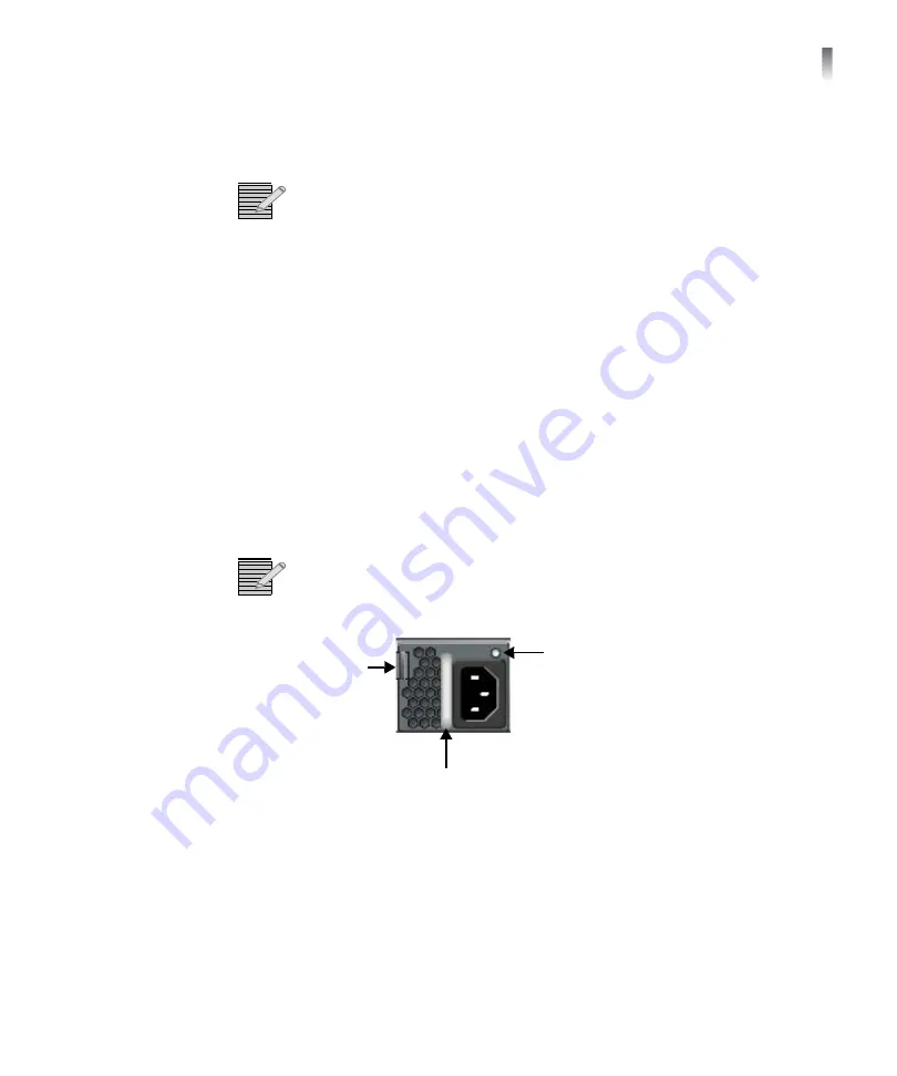
To identify and remove the failed power supply
Release
Tab
Handle
Status
LED
Figure 1-3
Power Supply Module
1
Look at the status LED on the front of each power supply. The LED on the
failed power supply will not be illuminated.
2
To remove a power supply, push the release tab to the left.
3
Hold the release tab to the left, grasp the power supply handle, and pull
the power supply out of the frame.
Summary of Contents for NEXIO NX1010 series
Page 23: ...NEXIO NX1010 Series Hardware Guide 19 Figure 1 6 Sample NX1010MGX Topology...
Page 25: ...NEXIO NX1010 Series Hardware Guide 21 Figure 1 7 Sample NX1010MIOH Topology...
Page 26: ...Chapter 1 Installation 22 Figure 1 8 Sample NX1010MIOH Topology with Intrinsic Mirroring...
Page 28: ...Chapter 1 Installation 24 Figure 1 9 Sample NX1010FCP Topology for Direct Connection to MACs...
Page 31: ...NEXIO NX1010 Series Hardware Guide 27 Figure 1 11 Sample NX1010PTCD Topology...
Page 32: ...Chapter 1 Installation 28...
Page 48: ...Chapter 3 Monitoring Status 44...
Page 54: ...Chapter 4 Troubleshooting 50...


