Doc no: 430-041-01
13 of 64
Note that Hypack adopts a different convention in the vertical (Z). See below from the Hypack systems
manual:
The vertical offset is the distance below the static waterline of the vessel. This is the waterline
location when the boat is stationary. Of course, this point changes under various conditions (weight
of passengers, fuel and cargo), but you have to start somewhere. Enter the antenna height above
the water line as a negative value. The distance from the waterline to the transducer head
will be positive.
In addition to the Z offset between the CRP and the receiving transducer of the MBES, the transducer
elevation with respect to the water surface (static transducer draft) should be measured. Most surveys will
seek to determine the depth between tidally corrected mean sea level and mean seabed. In order to achieve
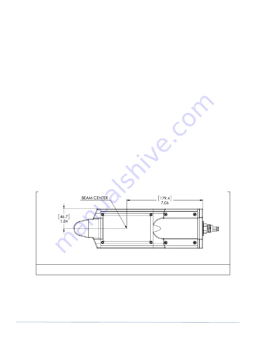
this, the distance between transducer acoustic centre (Figure 3-5 Acoustic centre of transducer ([mm] and
inches) and mean sea level must be known, which will necessarily change with fuel and water consumption,
ballasting, sea water density and vessel speed through the water.
If possible, this Z value shou
ld be measured with respect to the vessel’s draft marks in dry dock and a table
created. This table should be referenced during operations and values updated in the log to compensate for
draft changes (as a result of fuel used for example). If such measurements cannot be taken, it is
recommended that elevation between transducer and sea level be measured as closely as possible to
operational vessel loaded conditions.
To ensure maximum accuracy, vessel settlement (squat or lift), which is a function of the vessels speed
through the water, may need to be measured. This is because the vertical component of this motion is the
bandwidth of the heave sensor’s high pass filter, and therefore not measurable. The evaluation of the ship's
settlement should be made for various speeds (or RPMs) and a look-up table should be produced, to be used
for correcting the transducer draught. Since the settlement varies with the speed of the vessel on the water,
surface velocity (not the speed over ground) should be obtained with the aid of an accurate log. [The
Calibration of Shallow Water Multibeam Echo-Sounding Systems
– A Godin, March 1998].
Note: Systems are commercially available that measure draft, squat and lift in different locations around the
vessel and model the vessel
’s attitude as a result of changes in water density, vessel speed, vessel load,
etc., and output a real time depth difference between the water surface and a datum point (for example the
MBES acoustic centre).
Figure 3-5 Acoustic centre of transducer ([mm] and inches)
Note: The Z reference point is the transducer face.
The survey platform CRP should be physically marked and identified on the vessel for further reference, if
possible, and the marking should be made permanent. If it is not possible to mark the exact location of the
point (e.g. in a void space), a remote point can be marked and the actual CRP be referred to this remote
point by XYZ offsets. The offsets should be physically indicated (magnitude and direction) near the remote
reference point. [The Calibration of Shallow Water Multibeam Echo-Sounding Systems
– A Godin, March
1998]
Summary of Contents for DT101Xi
Page 35: ...Doc no 430 041 01 35 of 64 APPENDIX A DT101Xi DT102Xi SPEC SHEETS DT101Xi...
Page 36: ...Doc no 430 041 01 36 of 64...
Page 37: ...Doc no 430 041 01 37 of 64...
Page 38: ...Doc no 430 041 01 38 of 64...
Page 39: ...Doc no 430 041 01 39 of 64 DT102Xi...
Page 40: ...Doc no 430 041 01 40 of 64...
Page 41: ...Doc no 430 041 01 41 of 64...
Page 42: ...Doc no 430 041 01 42 of 64...
Page 52: ...Doc no 430 041 01 52 of 64 Figure 6 7 Jumpers for Heading and PPS Selection...
Page 56: ...Doc no 430 041 01 56 of 64 Figure 6 8 Power Supply Voltage Option...


